Brushless motor control method and brushless motor

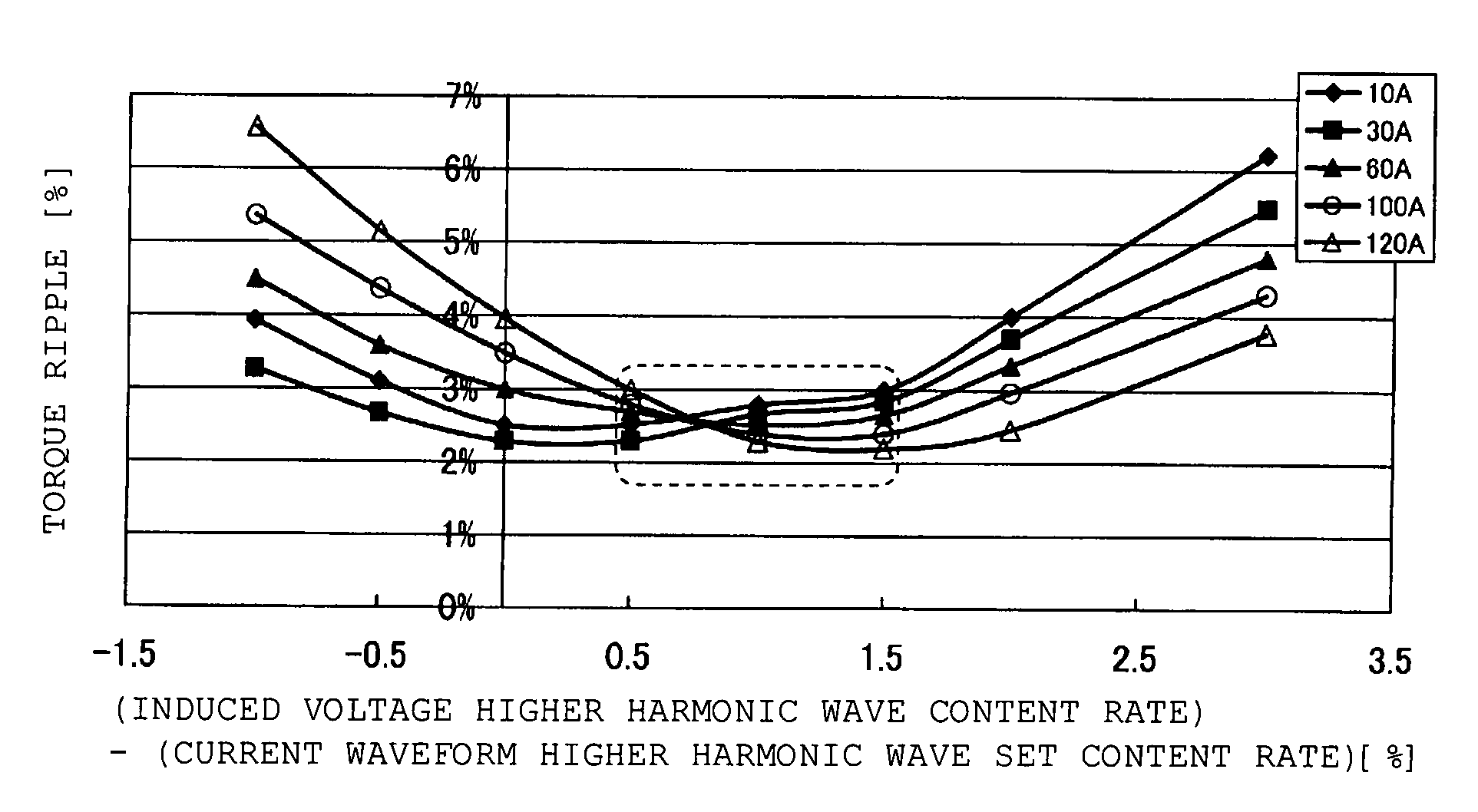
a brushless motor and control method technology, applied in the direction of motor/generator/converter stopper, electronic commutator control, motor/generator/converter stopper, etc., can solve the problems of deterioration of steering feeling, increased torque variation at higher current (higher load) side, and varied torque, so as to suppress the torque ripple, reduce the noise of motor operation, and suppress the effect of changes in the operation noise within the operating region

Active Publication Date: 2011-11-01
MITSUBA CORP
View PDF12 Cites 2 Cited by
  • Summary
  • Abstract
  • Description
  • Claims
  • Application Information

AI Technical Summary

Benefits of technology

[0022]According to the method of controlling a brushless motor of the present invention, the current that contains the higher harmonic component is supplied to the armature coil of the brushless motor including the stator having the armature coil and the rotor provided with the permanent magnet and is rotatably arranged at the inside or outside of the stator. Also, the given amount of difference is provided between the higher harmonic component content rate of the armature coil current and the higher harmonic component content rate of the induced electromotive force which is generated in the armature coil with the rotation of the permanent magnet. As a result, the current waveform of the armature coil is corrected in correspondence with the induced voltage waveform at the time of energization, and the influence of the armature reaction that is generated in the induced electromotive force is mitigated, thereby making it possible to suppress the torque ripple. For that reason, the motor operation noises may be reduced, and changes in the operation noises within the operating region may be suppressed.
[0023]Thus, the application of the control method of the present invention to the EPS motor allows the torque variation of the motor to be suppressed even if the motor load is varied according to the road surface conditions, thereby allowing a reduction in the motor operation noises. For that reason, the silent and stable steering operation may be conducted to improve the steering feeling.
[0024]According to the brushless motor of the present invention, the current containing the higher harmonic component is supplied to the armature coil in the brushless motor including the stator having the armature coil and the rotor having the permanent magnet and is rotatably arranged at the inside or outside of the stator. Also, the given amount of difference exists between the higher harmonic component content rate of the armature coil current and the higher harmonic component content rate of the induced electromotive force which is generated in the armature coil with the rotation of the permanent magnet. As a result, the current of the waveform that has been corrected in correspondence with the induced voltage waveform at the time of energization may be supplied to the armature coil, and the influence of the armature reaction that is generated in the induced electromotive force is mitigated, thereby being capable of suppressing the torque ripple. For that reason, the motor operation noises may be reduced, and changes in the operation noises within the operating region may be suppressed.
[0025]Consequently, the application of a brushless motor of the present invention to the EPS motor allows the torque variation of the motor to be suppressed even if the motor load is varied according to the road surface conditions, thereby being possible to reduce the motor operation noises. For that reason, the silent and stable steering operation may be conducted to improve the steering feeling.

Problems solved by technology

For that reason, there arises such a problem that the torque is varied, and particularly the torque variation at higher current (higher load) side is increased.
In particular, when the motor of the above type is used for the EPS, there arises such a problem that the operation noises continuously change, thereby causing a deterioration of the steering feeling because a load that is applied to the motor changes according to the travel state in the EPS.

Method used


Image

  • Brushless motor control method and brushless motor
  • Brushless motor control method and brushless motor
  • Brushless motor control method and brushless motor

Examples


Embodiment Construction

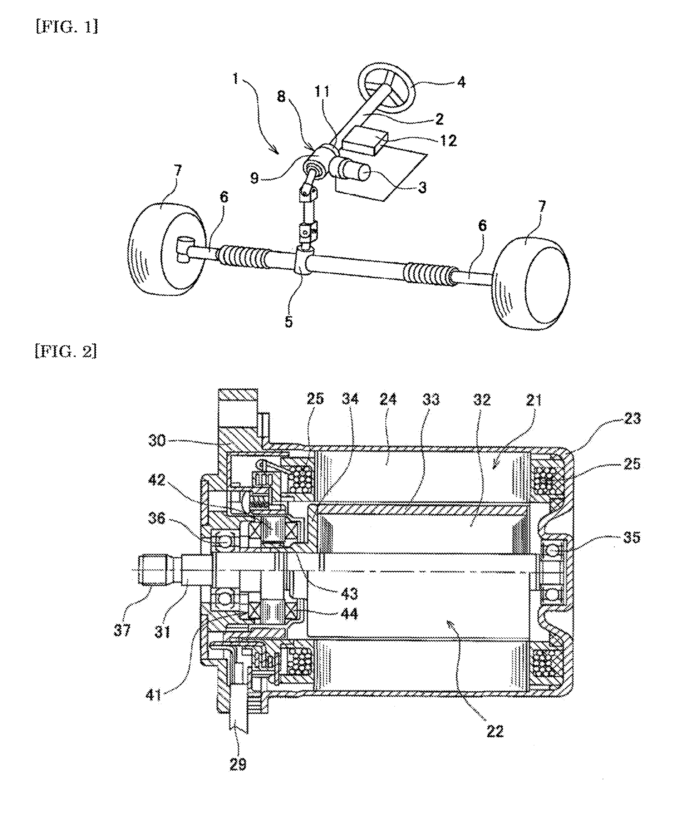
[0064]Hereinafter, a description is given of an embodiment of the present invention with reference to the drawings. FIG. 1 is a perspective view showing a configuration of an electric power steering device using a brushless motor according to the present invention. An electric power steering device (EPS) 1 shown in FIG. 1 is a column assist type in which an operating assist force is supplied to a steering shaft 2. In the EPS 1, a motor 3 to which the control method according to the present invention is applied is used as a power source.

[0065]A steering wheel 4 is fixed to the steering shaft 2. The steering force of the steering wheel 4 is transmitted to tie rods 6 through a pinion and a rack shaft (not shown) which are arranged within a steering gear box 5. Wheels 7 are connected to both ends of the tie rods 6. When the tie rods 6 operate with the operation of the steering wheels 4, the wheels 7 are steered right and left through knuckle arms (not shown).

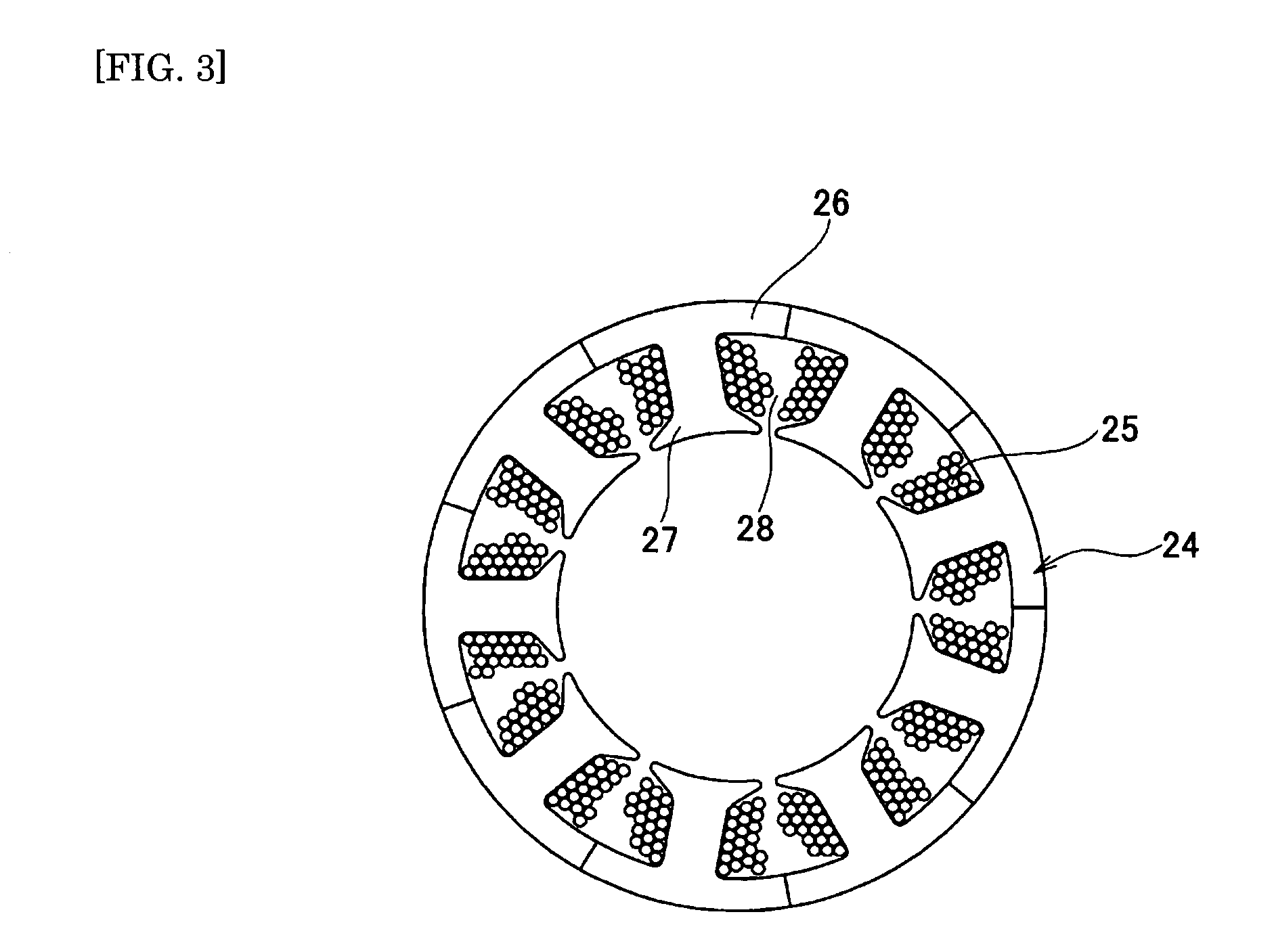
[0066]In the EPS 1, an assis...


PUM


Abstract

In a brushless motor for an electric power steering device having a configuration of 2 poles and 3 slots, or of an integral multiple thereof, a stator coil is supplied with current containing a higher harmonic component. A difference of 0.5% to 1.5% is provided between the higher harmonic component content rate of the stator coil current and the higher harmonic component content rate of the induced electromotive force generated in the stator coil with rotation of a permanent magnet, thereby mitigating the influence by an armature reaction generated in the induced electromotive force to reduce torque ripples. The difference between the higher harmonic component content rates is set on the basis of a change that occurs in the induced electromotive force due to the armature reaction at a time of supplying electricity to the armature coil.

Description

BACKGROUND OF THE INVENTION[0001](1) Field of the Invention[0002]The present invention relates to a brushless motor and a method of controlling a brushless motor, and more particularly to a technique that may be effectively applied to a brushless motor for an electric power steering device.[0003](2) Description of Related Art[0004]In order to assist a steering force of an automobile, in recent years, a large number of vehicles are provided with so-called power steering devices. As the power steering devices of this type, in recent years, the number of vehicles to which electric type power steering devices (so-called electric power steering device, hereinafter appropriately abbreviated as “EPS”) are mounted is increasing from the viewpoints of a reduction in engine load or a reduction in weight. As a power source of the EPS, motors with brushes have been used much hitherto. In recent years, however, the brushless motors have been increasingly used because of excellent maintenance pro...

Claims


Application Information

Patent Timeline
Patent Type & Authority Patents(United States)
IPC IPC(8): H02P6/10
CPCB62D5/046H02P6/10H02P29/0038H02P2209/07H02P29/50
Inventor OKUBO, MASAYUKIYAMAZAKI, TAKESHISHIKINE, YOUICHIROU
Owner MITSUBA CORP
Why Eureka
Try Eureka