Electromagnetic device

a technology of electromagnetic field and rotor, which is applied in the direction of dynamo-electric components, dynamo-electric machines, magnetic circuit shapes/forms/construction, etc., can solve the problems of complex structure of rotor, inability to effectively use the magnetic field generated by permanent magnets, vibration and noise generation in electric motors, etc., and achieve the suppression of heat generation in the coil, the effect of suppressing the increase in eddy current loss

Active Publication Date: 2020-07-30
KOGAKUIN UNIVERSITY
View PDF0 Cites 8 Cited by
  • Summary
  • Abstract
  • Description
  • Claims
  • Application Information

AI Technical Summary

Benefits of technology

[0025]These aspects of the present invention employ Litz wire in the coils, thereby enabling an increase in eddy current loss to be suppressed, and enabling heat generation in the coils to be suppressed.

Problems solved by technology

In a N-S field system, a magnetic field is produced at both sides of the arrayed magnets, such that the magnetic field generated by the permanent magnets is not able to be used effectively.
However, torque ripple produced in rotors cause vibration and noise to be generated in electric motors.
Thus in an electric motor employing a dual Halbach array field system, the structure of the rotor is complicated, and there is a concern regarding vibration and noise generated at high rotation speeds.
Moreover, in an electric motor employing a dual Halbach array field system, the armature coils are disposed inside the rotor of double cylinder structure, resulting in heat not being readily dissipated, and in problems due to the heat generated by the armature coil etc.

Method used


Image

  • Electromagnetic device
  • Electromagnetic device
  • Electromagnetic device

Examples


first exemplary embodiment

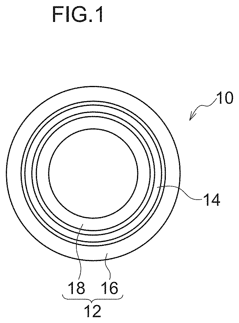
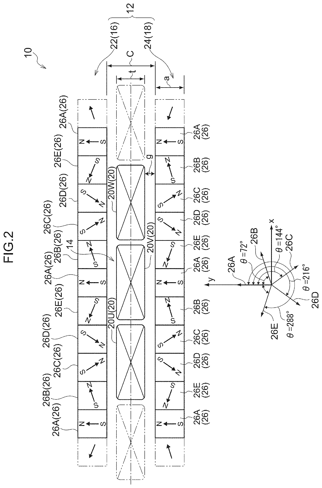
[0054]FIG. 1 illustrates main parts of a three-phase AC motor (hereafter referred to as electric motor 10) serving as an electromagnetic device according to a first exemplary embodiment, illustrated in plan view along an axial direction. The electric motor 10 is equipped with a field system 12 and an armature 14. The field system 12 and the armature 14 are housed in a non-illustrated casing (case).

[0055]The field system 12 is formed by an outside field system unit 16 and an inside field system unit 18, which both have a substantially cylindrical shape. The outside field system unit 16 configures an outside field system and the inside field system unit 18 configures an inside field system. The inner diameter of the outside field system unit 16 is larger than the outer diameter of the inside field system unit 18. The outside field system unit 16 and the inside field system unit 18 are coaxially disposed in the field system 12, with the inside field system unit 18 housed inside the out...

second exemplary embodiment

[0103]Detailed explanation follows regarding a second exemplary embodiment of the present invention.

[0104]FIG. 10 illustrates a schematic configuration of main parts of a three-phase AC motor (hereafter referred to as electric motor 60) serving as an electromagnetic device and a rotary electrical machine according to a second exemplary embodiment, as seen in a plan view along the axial direction.

[0105]The electric motor 60 is equipped with an external diameter pillar shaped rotor 62 as a rotor, and a substantially cylindrical shaped stator 64 serving as a stator configuring an armature. In the electric motor 60, the rotor 62 and the stator 64 are coaxially disposed, with the rotor 62 disposed inside the stator 64 and supported by the stator 64 so as to be capable of rotating.

[0106]A field system unit 66 is provided at an outer peripheral portion of the rotor 62. A cylindrical shaped outer cylinder section 68 is provided to the stator 64 as a magnetic path forming section. The outer ...


PUM


Abstract

In an electric motor, three-phase coils are provided to an armature disposed between an outside field system and an inside field system, and Halbach arrays are employed in the outside field system and the inside field system. Each of the Halbach arrays is divided by a number of divisions that is any number computed by adding two to a multiple of three. Permanent magnets are arrayed such that their magnetization directions are changed in sequence by steps of an angle computed by dividing one cycle's worth of electric angle by the number of divisions. Torque ripple is thereby suppressed in the electric motor.

Description

TECHNICAL FIELD[0001]The present invention relates to an electromagnetic device such as a rotary electrical machine or the like.BACKGROUND ART[0002]There are electromagnetic devices, such as linear motors, rotary electrical machines like a rotary electric motor or generator etc., and the like, in which a field system resulting from alternately arraying N poles and S poles of permanent magnets (a N-S array field system) is employed. In a N-S field system, a magnetic field is produced at both sides of the arrayed magnets, such that the magnetic field generated by the permanent magnets is not able to be used effectively.[0003]In order to address this issue, a Halbach array is sometimes employed as a method to array permanent magnets so as to raise the magnetic field produced by the field system. A Halbach array is a method to array magnets in which permanent magnets are arrayed while rotating the magnetic poles (magnetization direction) of the permanent magnets by steps of 90°. This en...

Claims


Application Information

Patent Timeline
Patent Type & Authority Applications(United States)
IPC IPC(8): H02K1/27H02K3/47H02K21/14
CPCH02K3/47H02K21/14H02K1/278H02K41/031H02K2213/03H02K16/02H02K1/2786
Inventor MORISHITA, MIMPEI
Owner KOGAKUIN UNIVERSITY
Why Eureka
Try Eureka