Multi-plate clutch

a multi-plate, clutch technology, applied in the direction of fluid actuated clutches, non-mechanical actuated clutches, clutches, etc., can solve the problems of heat spots partially generated, driven plates may be deformed, and affect the operation and endurance of the clutch, so as to achieve stable operation, suppress heat spots on the driven plates, and the effect of increasing the cos

Active Publication Date: 2006-09-14
NSK WARNER
View PDF3 Cites 4 Cited by
  • Summary
  • Abstract
  • Description
  • Claims
  • Application Information

AI Technical Summary

Benefits of technology

[0013] Heat spots on the driven plates can be suppressed and a stable operation can be maintained, with a compact construction without increasing the cost. That is to say, on the basis of a configuration of the urging surface of the piston, ability for resisting to the heat spot of the driven plate can be enhanced, and, more particularly, generation of the heat spot can be suppressed by providing convex or protruded portions on the piston in correspondence to the arrangement of the spline portions and by urging the driven plate by means of such protruded portions.

Problems solved by technology

Accordingly, the heat spot may cause shudder or may affect a bad influence upon the operation and endurance of the clutch.
Further, if the splines of the driven plates are not positioned equidistantly, when the piston of the multi-plate clutch urges the driven plates, since there is difference in rigidity between the spline portions and non-spline portions of the driven plates, the driven plates may be deformed, with the result that the heat spots may partially be generated on urging surfaces corresponding to the non-spline portions.
However, as shown in the above-mentioned Japanese Patent Application Laid-open No. 9-287622, the fact that a plurality of driven plates having different thicknesses are prepared for one multi-plate clutch may lead in increase in cost, thereby causing a new problem.

Method used


Image

  • Multi-plate clutch
  • Multi-plate clutch
  • Multi-plate clutch

Examples


Embodiment Construction

[0017] Now, embodiments of the present invention will be fully explained with reference to the accompanying drawings. Incidentally, in the drawings, the same parts or elements are designated by the same reference numerals. Further, it should be noted that the embodiments which will be described hereinbelow are merely examples of the present invention and do not limit the present invention.

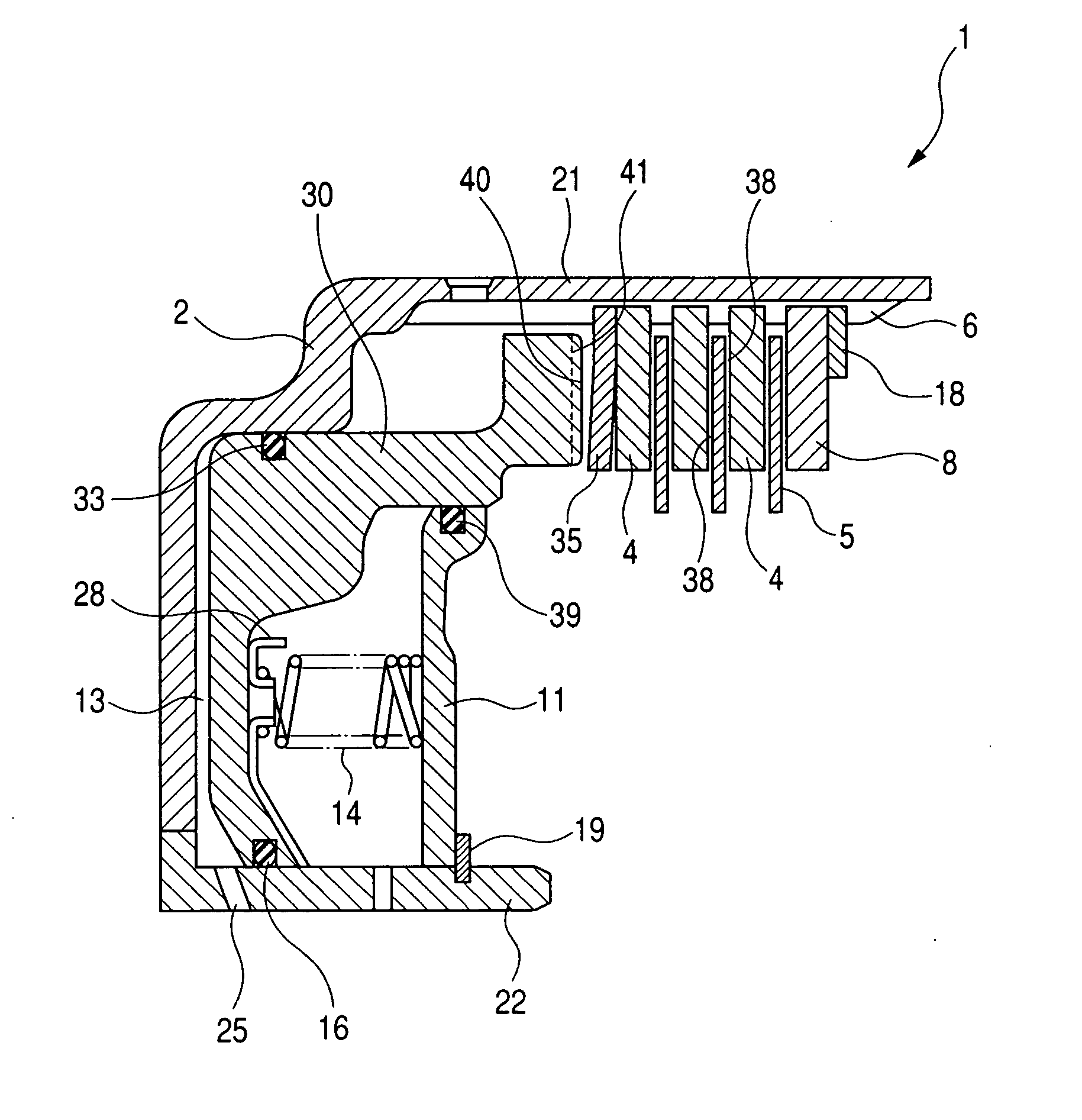
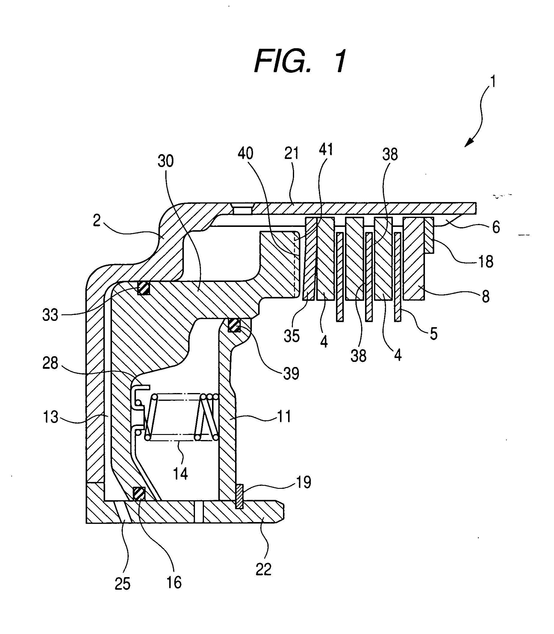
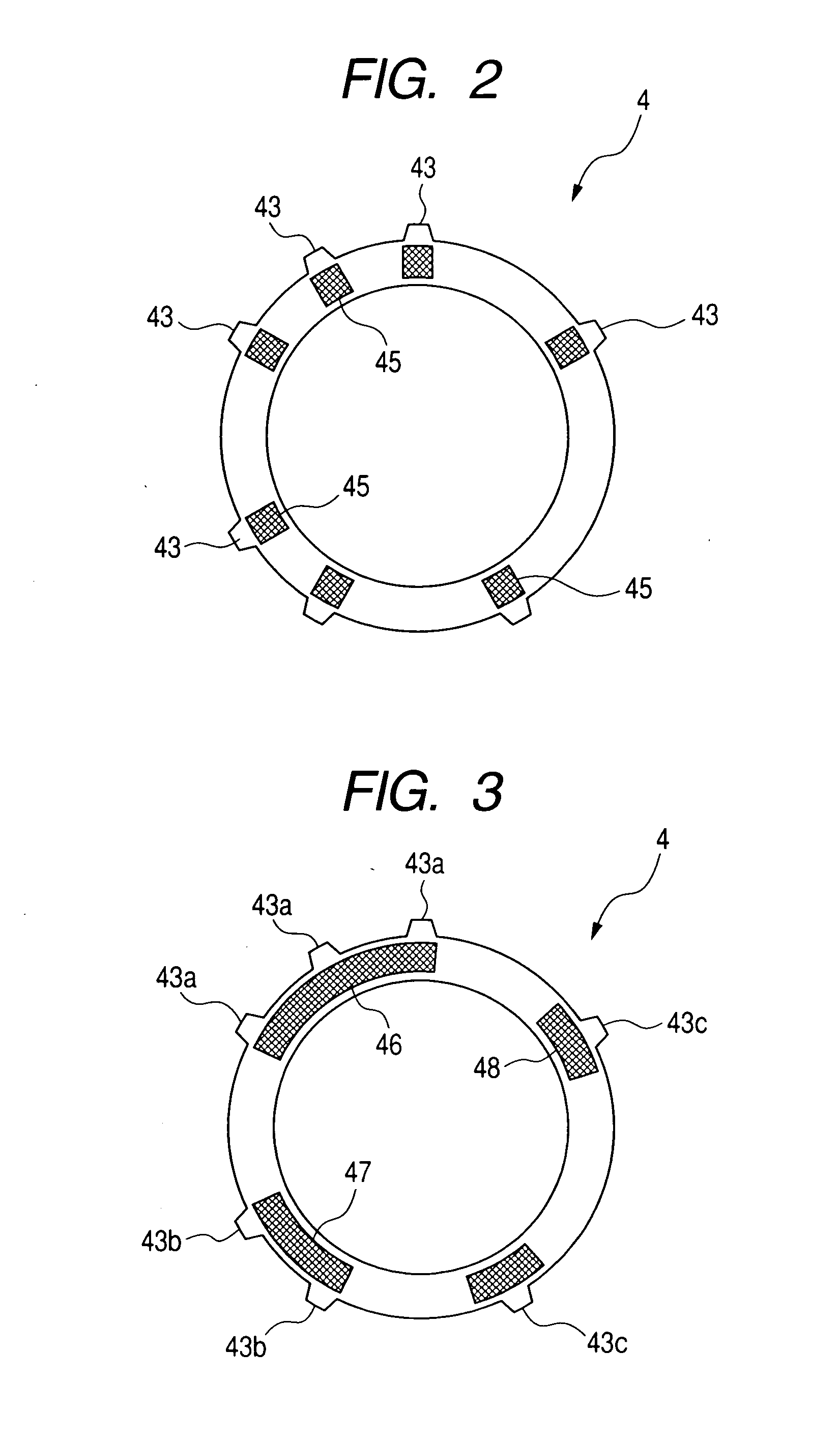
[0018]FIG. 1 is an axial sectional view showing an embodiment of a multi-plate clutch 1 according to the present invention, and FIG. 2 is a front view of a separator plate used in the multi-plate clutch of the present invention, showing urged areas urged by a piston. Further, FIG. 3 is a front view of a separator plate used in the multi-plate clutch of the present invention, showing another example of urged areas urged by a piston.

[0019] In the multi-plate clutch 1, a clutch case 2 and a hub (not shown) are arranged on a common axis. A spline 6 is formed in an inner peripheral surface of an outer...


PUM


Abstract

The present invention provides a multi-plate clutch comprising drive plates which are coaxially disposed within a clutch housing and to which friction materials are fixed, driven plates which are alternately arranged with the drive plates and a piston having an urging surface for providing an axial load to engage the drive plates and the driven plates with each other and wherein a plurality of urging portions protruding toward the driven plate are formed on the urging surface of the piston and the urging portions are provided in correspondence to an arrangement of spline projections provided on an outer periphery of the driven plate un-equidistantly along a circumferential direction.

Description

BACKGROUND OF THE INVENTION [0001] 1. Field of the Invention [0002] The present invention relates to a multi-plate clutch used in an automatic transmission of a vehicle and the like. More particularly, the present invention relates to a multi-plate clutch in which a relative relationship between urging portions of a piston and spline positions of driven plates are regulated. [0003] 2. Related Background Art [0004] In a multi-plate clutch, a power is transmitted by engaging a plurality of friction engaging elements disposed within a clutch housing with each other. Within the clutch housing, a piston movable in an axial direction is provided for applying an axial urging force to the friction engaging elements to engage them with each other. [0005] In the multi-plate clutch, it is designed so that driven plates (separator plates) and drive plates (friction plates), which serve to act as the friction engaging elements, are alternately arranged in an overlapped fashion, whereby the multi...

Claims


Application Information

Patent Timeline
Patent Type & Authority Applications(United States)
IPC IPC(8): F16D25/0638F16D13/52
CPCF16D13/52F16D13/648F16D13/70F16D25/0638F16D25/12F16D2048/0212
Inventor KINPARA, HIROYUKI
Owner NSK WARNER
Why Eureka
Try Eureka