Displacement detecting device

a technology of displacement detection and detection device, which is applied in the direction of measurement device, optical conversion of sensor output, instruments, etc., can solve the problems of reducing sensitivity, affecting method, and decreasing measurement resolution, so as to reduce heat generation, expand the application of the device, and narrow the effect of the area

Active Publication Date: 2015-10-15
DMG MORI CO LTD
View PDF17 Cites 3 Cited by
  • Summary
  • Abstract
  • Description
  • Claims
  • Application Information

AI Technical Summary

Benefits of technology

[0014]According to the displacement detecting device of the present invention, a conventional driving mechanism is not needed, whereby it is possible to suppress heat generated at the time of operation. Furthermore, there is no need to drive the driving mechanism, and thus it is possible to solve the problem concerning response frequency, whereby it is possible to expand applications of the device.
[0015]Moreover, since the reflection / transmission section guides the first light beam to a specific position of the member to be measured, it is possible to overlap the optical paths of the first light beam entering the surface to be measured of the member to be measured. This makes it possible to measure one specific point on the surface to be measured, and thus it is possible to measure a much narrower area on the surface to be measured.
[0016]In addition, the optical path length of the first light beam and the optical path length of the second light beam are set equal to each other. Therefore, it is possible to equalize the effects thereof on the first light beam and the second light beam even if the wavelength of the light source varies due to a change in atmospheric pressure, humidity, and temperatures. As a result, there is no need to make atmospheric pressure correction, humidity correction, and temperature correction, and thus it is possible to stably make measurements.

Problems solved by technology

However, this method is largely affected by a slope of the surface to be measured, and reduces sensitivity, which leads to a problem of decreasing resolution in measurement with the increase in an area to be measured.
However, with an increase in the area to be measured, this method is affected by the change in the wavelength of a light source and the change in the index of refraction of air.

Method used


Image

  • Displacement detecting device
  • Displacement detecting device
  • Displacement detecting device

Examples


first exemplary embodiment

1. Displacement Detecting Device

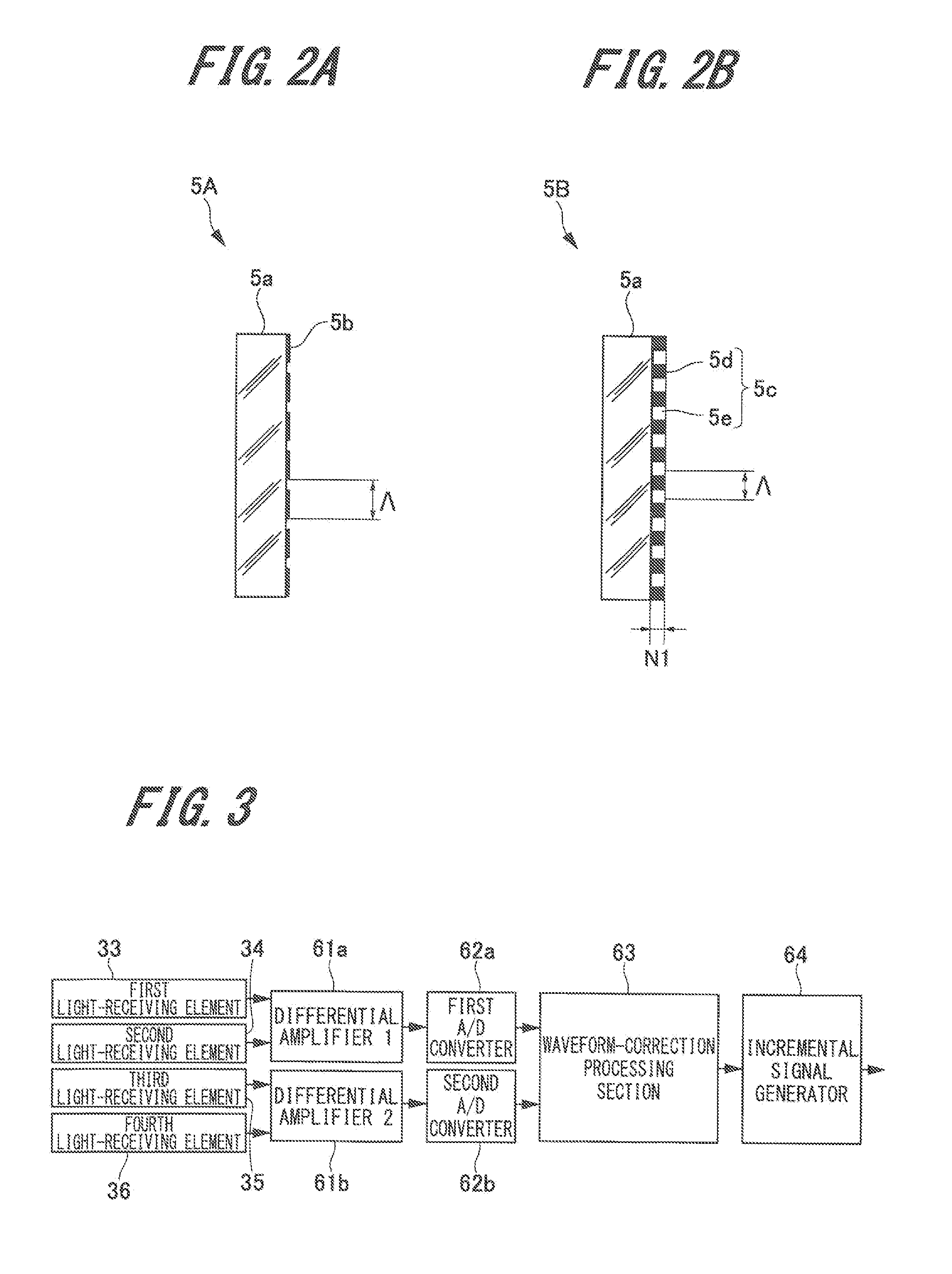
[0027]First, the configuration of the displacement detecting device according to the first exemplary embodiment of the present invention (hereinafter, referred to as “this embodiment”) will be described with reference to FIG. 1 to FIG. 3.

1-1. Configuration Example of Displacement Detecting Device

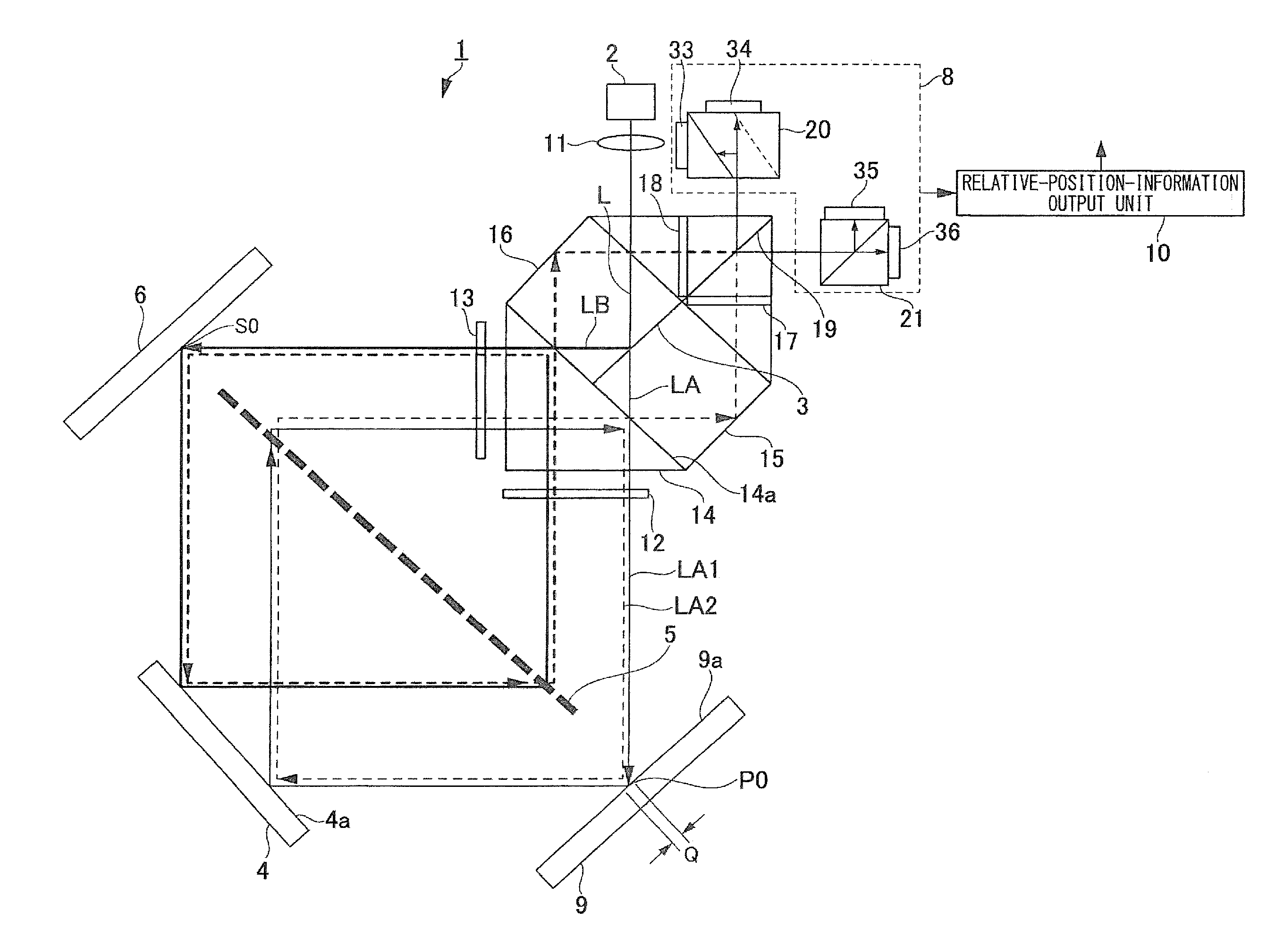
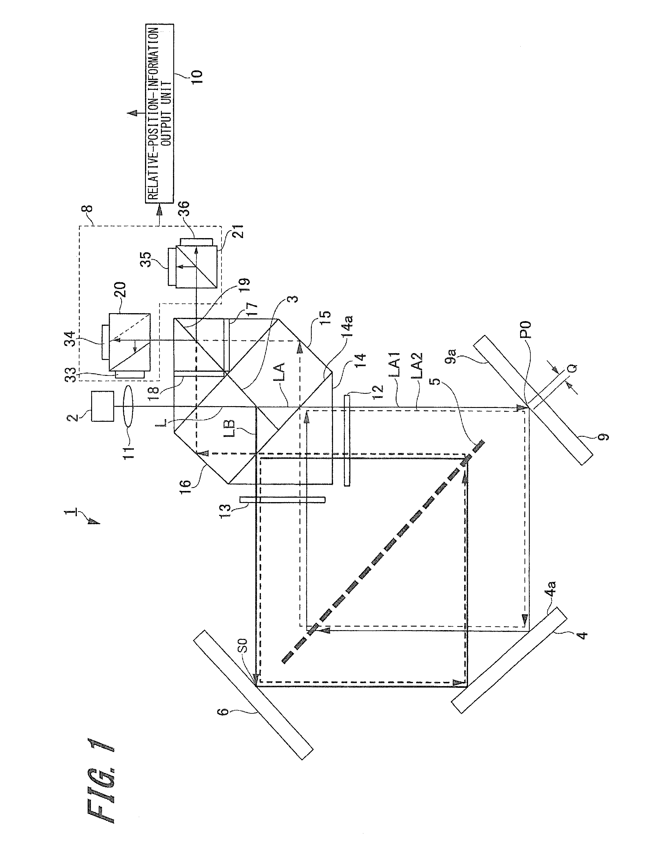
[0028]FIG. 1 is a schematic configuration diagram illustrating a configuration of the displacement detecting device.

[0029]The displacement detecting device 1 according to this embodiment can detect displacement in the vertical diction on a surface to be measured by using a transmission-type diffraction grating. As illustrated in FIG. 1, the displacement detecting device 1 includes a light source 2, a light-beam splitting section 3 that splits light emitted from the light source into two light beams LA and LB, a transmission-type diffraction grating 5, a mirror 4, which is one example of a reflection member, a reference reflection section 6, and a light-receivi...

second exemplary embodiment

2. Second Exemplary Embodiment

[0108]Next, a displacement detecting device according to a second exemplary embodiment will be described with reference to FIG. 5.

[0109]FIG. 5 is a schematic configuration diagram illustrating a configuration of the second exemplary embodiment.

[0110]The displacement detecting device 100 according to the second exemplary embodiment differs from the displacement detecting device 1 according to the first exemplary embodiment in that a mirror 104 for the first light beam and a mirror 105 for the second light beam are provided as reflection members. Accordingly, here, the mirror 104 for the first light beam and the mirror 105 for the second light beam will be described. In addition, the same reference signs are attached to portions common to those of the displacement detecting device 1 according to the first exemplary embodiment, and explanation thereof will be omitted.

[0111]As illustrated in FIG. 5, the mirror 104 for the first light beam and the mirror 105...

third exemplary embodiment

3. Third Exemplary Embodiment

[0116]Next, a displacement detecting device according to a third exemplary embodiment will be described with reference to FIG. 6.

[0117]FIG. 6 is a schematic configuration diagram illustrating a configuration of the second exemplary embodiment.

[0118]This displacement detecting device 200 according to the third exemplary embodiment differs from the displacement detecting device 1 according to the first exemplary embodiment in that a combining-section-side reflection / transmission section is provided in place of the reflection member. Accordingly, in this exemplary embodiment, the combining-section-side reflection / transmission section will be described. Furthermore, the same reference signs are attached to portions common to those of the displacement detecting device 1 according to the first exemplary embodiment, and explanation thereof will be omitted.

[0119]As illustrated in FIG. 6, the displacement detecting device 200 includes a reflection / transmission se...


PUM


Abstract

A displacement detecting device includes a light source that performs irradiation with light, a light-beam splitting section, a reflection/transmission section, a phase plate, a transmission-type diffraction grating, a light-beam combining section, a light-receiving section, and a relative position information output unit. The reflection/transmission section transmits or reflects a first light beam, and causes the beam to enter a member to be measured. Furthermore, the reflection/transmission section guides the first light beam to a specific position of the member to be measured in the case where the member to be measured is in a reference position. Moreover, an optical path of the first light beam reflected by the member to be measured again overlaps with an optical path of the first light beam reflected at a specific position of the member to be measured.

Description

BACKGROUND OF THE INVENTION[0001]1. Field of the Invention[0002]The present invention relates to a displacement detecting device that detects displacement of a surface to be measured with a noncontact sensor using light emitted from a light source, more specifically, to a technique of detecting displacement in a direction perpendicular to the surface to be measured.[0003]2. Description of the Related Art[0004]Conventionally, displacement detecting devices using light have been widely utilized as a device measuring displacement or shape of a surface to be measured in a noncontact manner. A typical example thereof includes a method of irradiating the surface to be measured with laser light to thereby detect positional changes of the reflected light by using PSD. However, this method is largely affected by a slope of the surface to be measured, and reduces sensitivity, which leads to a problem of decreasing resolution in measurement with the increase in an area to be measured.[0005]In ...

Claims


Application Information

Patent Timeline
Patent Type & Authority Applications(United States)
IPC IPC(8): G01B11/14
CPCG01B11/14G01B9/02022G01B9/02081G01B2290/70G01D5/34746G01D5/38
Inventor TAMIYA, HIDEAKI
Owner DMG MORI CO LTD
Why Eureka
Try Eureka