Anodizing apparatus

a technology of anodizing apparatus and anodizing heat, which is applied in the direction of manufacturing tools, electric circuits, electric circuits, etc., can solve the problems of difficult continuous anodizing operations, spark generation, and complex apparatus of patent document 5, so as to achieve stable contact resistance, reduce voltage and heat generation, and increase line speed

Inactive Publication Date: 2013-01-31
FUJIFILM CORP
View PDF2 Cites 4 Cited by
  • Summary
  • Abstract
  • Description
  • Claims
  • Application Information

AI Technical Summary

Benefits of technology

[0046]The anodizing apparatus of the present invention comprises: a power supplying drum for supporting a strip of an anodizable metal or a strip of a composite conductive metal foil having an anodizable metal on at least one surface thereof in close contact, at least a portion of the power supplying drum which is in close contact with the strip being constituted by a conductive material; opposing electrodes provided to face the power supplying drum; an electrolysis tank filled with an electrolytic solution in which a portion of the power supplying drum that supports the strip in close contact and the opposing electrodes are immersed; protective members formed by a non conductive material that overlaps the transverse ends of the strip supported by the power supplying drum in close contact and portions of the power supplying drum with which the strip is not in close contact to protect the ends and the portions of the power supplying drum from the electrolytic solution; and a drive section that causes the strip in close contact with the power supplying drum and the protective members to move together within the electrolytic solution, synchronized with the rotating speed of the power supply drum. Therefore, it is possible to completely prevent anodized coating film formation on the side of the strip in close contact with the power supplying drum, and an anodized coating film can be formed on a single surface of the strip with stable contact resistance.
[0047]In addition, the strip is supported in close contact by the power supplying drum, enabling direct power supply from the back surface of the strip. Therefore, voltage drops and heat generation can be suppressed to a level that can be ignored, enabling line speed to be increased. For this reason, an anodized coating film can be formed at high speed even if the resistance of the strip per length at a unit width is high.
[0048]Further, a recess that the strip contacts and moves within may be provided in the power supplying drum, or guide rollers for pressing the protective member on to the power supplying drum may be provided. In these cases, the waterproof properties of the portion at which the protective member overlaps the ends in the transverse direction of the strip and the portions of the power supply drum at which the strip is not in close contact with the power supply drum are improved. Therefore, an anodized coating film can be formed on a single surface of the strip with more stable contact resistance.

Problems solved by technology

However, the apparatus of Patent Document 5 is not only complex, but the electrolytic solution will be diluted by the water on the close contact surface, and therefore it is necessary to constantly maintain the concentration of the electrolytic solution.
As a result, there is a possibility that employing this apparatus will cause sparks to be generated.
Therefore, the positions of the bands are likely to shift away from the edges of the aluminum foil, and it is difficult for continuous anodizing operations to be performed.
In addition, wrinkles will be generated by the tension being applied under pressure in the case that the aluminum foil is thin, and there is a possibility that electrolytic solution will flow into the space between the aluminum foil and the drum through the wrinkled portions.
As described above, none of the methods described above can completely prevent anodized coating film formation on the side of the close contact surface.
Therefore, the problem that contact resistance will be unstable cannot be solved.

Method used


Image

  • Anodizing apparatus
  • Anodizing apparatus
  • Anodizing apparatus

Examples


Embodiment Construction

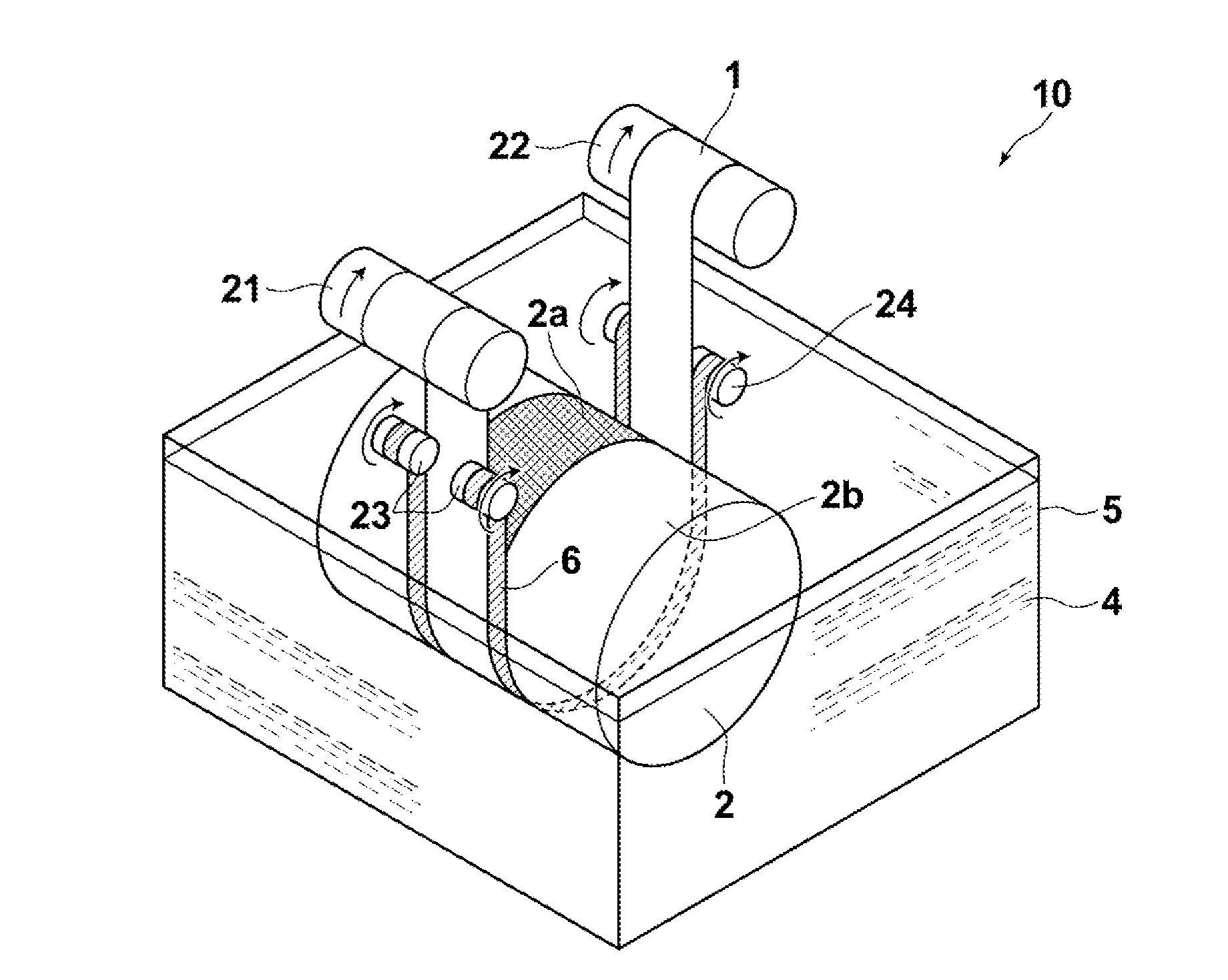
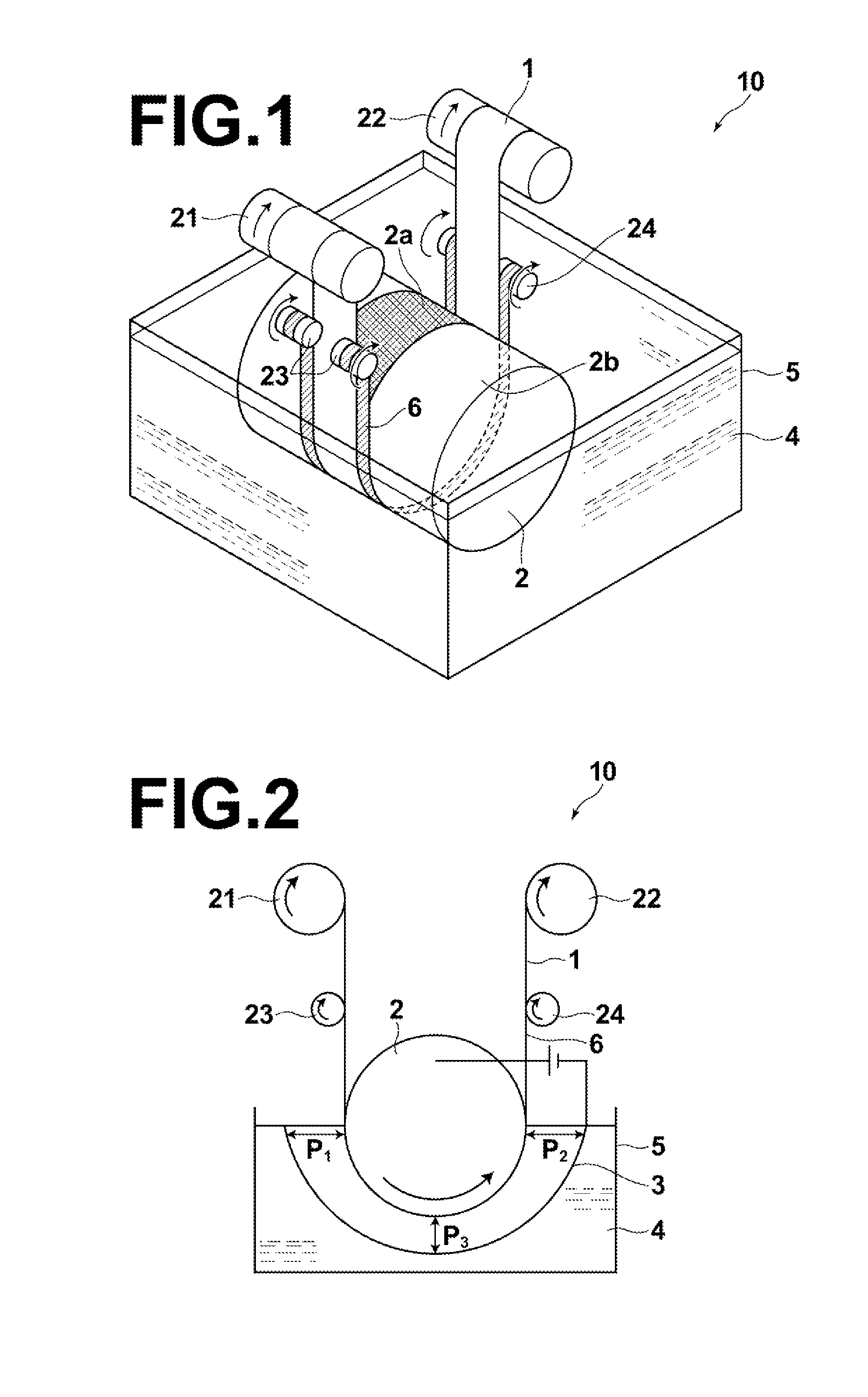
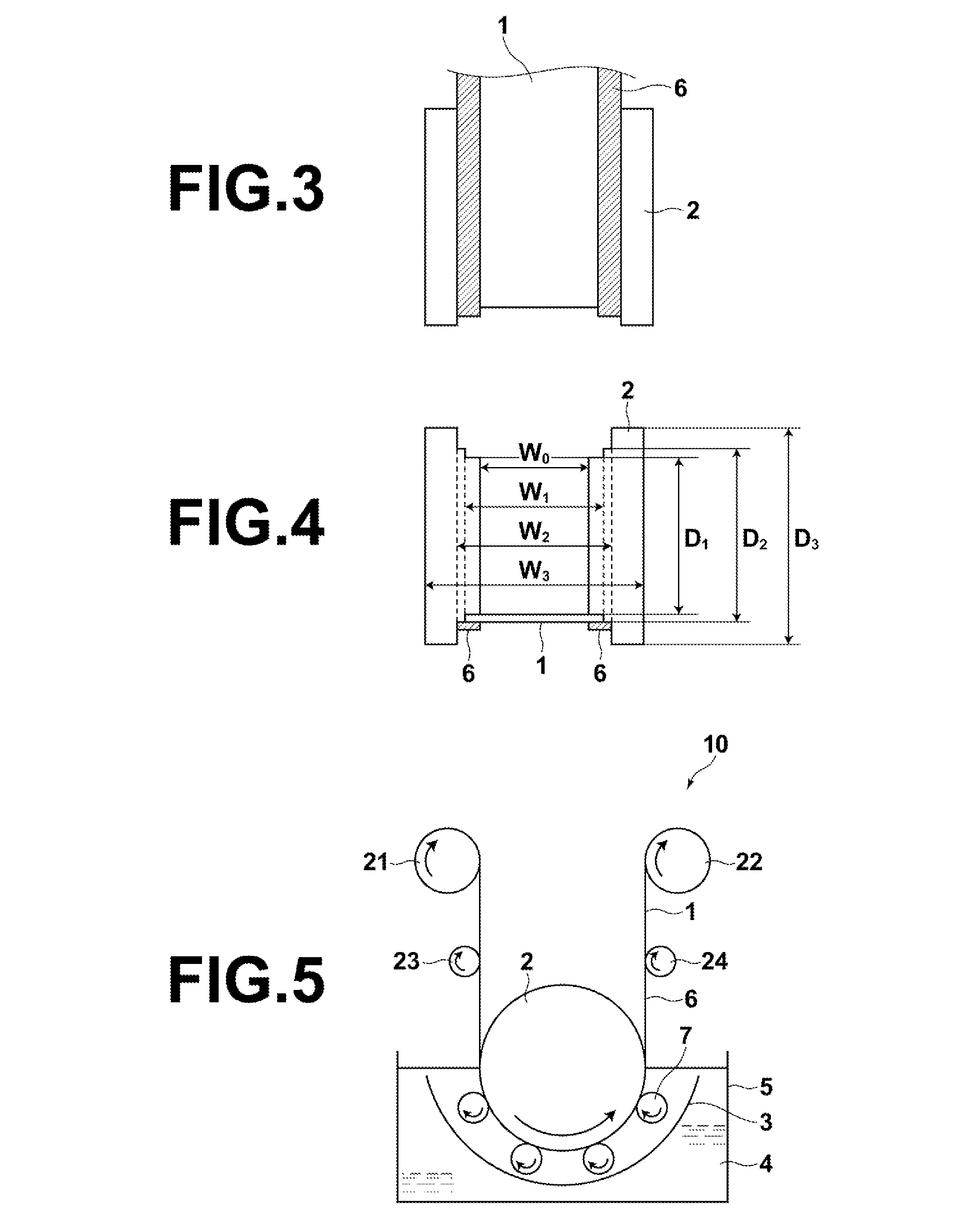
[0059]Hereinafter, anodizing apparatuses of the present invention will be described in detail with reference to the attached drawings. FIG. 1 is a schematic perspective view that illustrates an anodizing apparatus 10 according to an embodiment of the present invention. FIG. 2 is a schematic sectional view of the anodizing apparatus 10 of FIG. 1. As illustrated in FIG. 1 and FIG. 2, the anodizing apparatus 10 of the present invention includes: a power supplying drum 2 for supporting a strip 1 of an anodizable metal or a strip 1 of a composite conductive metal foil having an anodizable metal on at least one surface thereof (hereinafter, also simply referred to as “strip 1”) in close contact, at least a portion 2a of the power supplying drum which is in close contact with the strip 1 being constituted by a conductive material; opposing electrodes 3 provided to face the power supplying drum 2 (the opposing electrodes 3 is omitted from FIG. 1 in order to facilitate visual understanding o...


PUM

PropertyMeasurementUnit
temperatureaaaaaaaaaa
thicknessaaaaaaaaaa

Abstract

An anodizing apparatus includes: a power supplying drum for supporting a strip of an anodizable metal or a composite conductive foil having an anodizable metal on one surface thereof in close contact, at least a portion of the power supplying drum supporting the strip being conductive; opposing electrodes facing the power supplying drum; an electrolysis tank filled with an electrolytic solution in which a portion of the power supplying drum that supports the strip and the opposing electrodes are immersed; non conductive protective members that overlap the transverse ends of the strip on the power supplying drum and portions of the power supplying drum that the strip is not in contact with to protect the overlapped portions from the electrolytic solution; and a drive section that causes the strip and the protective members to move together within the electrolytic solution, synchronized with the rotating speed of the power supply drum.

Description

TECHNICAL FIELD[0001]The present invention is related to an anodizing apparatus suited for producing substrates for semiconductor elements and electrodes for electrolytic capacitors, which are used in semiconductor devices such as solar batteries, thin film transistor circuits and displays (image display devices).BACKGROUND ART[0002]There are greater possibilities for application of thin film solar batteries that employ metal substrates compared to those that employ glass substrates from the viewpoints of the light weight and the flexibility thereof. Further, there are expectations for higher efficiency of solar batteries because metal substrates can endure high temperature processes, therefore improving the photoelectric conversion properties thereof.[0003]The module efficiency of a solar battery module is improved by connecting solar battery cells in series on a single substrate and integrating the solar battery cells. At this time, it is necessary to form an insulating layer on t...

Claims


Application Information

Patent Timeline
Patent Type & Authority Applications(United States)
IPC IPC(8): C25D17/06C25D19/00C25D7/06C25D21/00
CPCC25D11/005C25D11/045
Inventor YUUYA, SHIGENORI
Owner FUJIFILM CORP
Why Eureka
Try Eureka