Bent type jack contact for crown spring

A socket contact, bending technology, applied in the direction of contact parts, parts of connecting devices, connections, etc., can solve the problem that the installation and use requirements of polar contacts cannot be met, and the difficulty of opening the base mold of the connector is high. , the protection tube and the pins are loose or fall off, etc., to achieve the effect of simple structure, good structure fixation and good consistency

Inactive Publication Date: 2012-09-19
ZUNYI JINGXING AEROSPACE ELECTRICAL APPLIANCE
View PDF4 Cites 7 Cited by
  • Summary
  • Abstract
  • Description
  • Claims
  • Application Information

AI Technical Summary

Problems solved by technology

[0003] 1. The protection tube and the pin in the traditional crown spring socket contact are fixed by riveting at intervals or adjoining the circumference. When the pin needs to be bent, the wall thickness of the protection tube is relatively thin (generally 0.2mm) , The strength of the riveting point cannot fully withstand the radial stress such as the end bending, and even the protective tube and pins loosen or fall off after bending, reducing the reliability of signal transmission;
[0004] 2. The socket contact can only be pressed into the base from the connector butt end, and cannot prevent rotation after being pressed in, and cannot meet the installation and use requirements of polar contacts (such as the orientation of the solder cup of the solder cup contact) If the above-mentioned problems are solved by processing the cut flat structure at the end of the protective tube, on the one hand, the efficiency of part processing will be reduced, and on the other hand, the size of the part will also be increased. When there are many rows of contacts in the connector (such as 6 rows), The design of bending tooling is difficult, and the bending quality is not high;
[0005] 3. The base for installing the contact piece needs to be equipped with step holes that match the steps of the pins, and requires coaxiality requirements with the holes for the protective tube and the holes for the pins, which makes it difficult to make the base mold of the connector higher

Method used


Image

  • Bent type jack contact for crown spring
  • Bent type jack contact for crown spring
  • Bent type jack contact for crown spring

Examples


Embodiment Construction

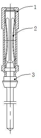
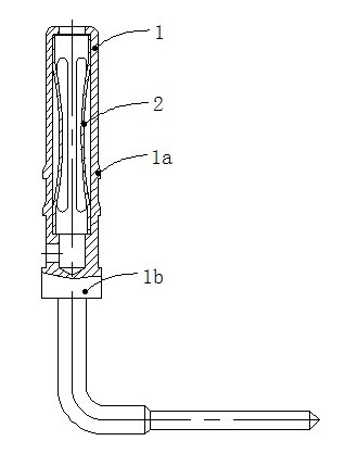
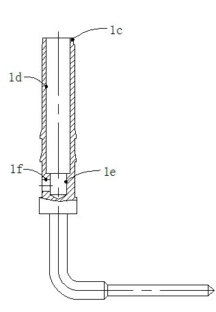
[0020] The specific structure of the crown spring receptacle contact in the present invention will be further described in detail below in conjunction with the accompanying drawings.

[0021] As shown in the figure, the bent crown spring jack contact of the present invention is composed of a bent jack 1 and a crown spring contact ring 2. There is no inner hole ld of the crown spring contact ring 2 installed at the end, and the crown spring contact ring 2 is fixed in the curved jack through the interference fit with the inner hole ld. The docking port of the curved socket 1 is provided with a turning riveting step 1c, and the outer ring surface of the docking end is provided with two rings of braces 1a at a certain distance corresponding to the base mounting hole, and there is a gap between the docking end and the tail end. The step 1b, the lower end of the inner hole 1d at the butt joint end is provided with a counterbore 1e and a radial side hole 1f passing through the counte...


PUM


Abstract

The invention provides a bent type jack contact for a crown spring. The bent type jack contact consists of a bent type jack and a crown spring type contact ring. The tail end of the bent type jack is in a 90-degree bent structure; no inner space for mounting the crown spring type contact ring exists in equipment at a butt-joint end; and the crown spring type contact ring is fixed in the bent type jack through interference fit of an inner hole. The bent type jack contact provided by the invention has the advantages of simple structure, high machining efficiency, high machining precision of the 90-degree bent part, good consistency, reliable signal transmission, simple assembly and good structure stability, and can be used for effectively ensuring the direction of a bending pin. The bent type jack contact is applicable to a bend-plug type circuit connector for a printed board, and has the advantages of smaller contact distance, light plug force requirement and large contact row quantity.

Description

technical field [0001] The invention relates to a jack contact structure of an electrical connector, belonging to the technical field of electrical connectors. Background technique [0002] With the increasingly complex installation and use environment of electrical connectors, higher and more requirements are put forward for the performance of electrical connector contacts. Not only does it require reliable signal transmission, but it should also have low insertion force, stable contact resistance, and vibration resistance. , impact resistance and other characteristics, the crown spring socket contact is a contact with better performance, and the current crown spring socket contact in the electrical connector is basically composed of a protective tube, a contact ring (crown spring hole), a straight type jacks or pins (such as figure 1 shown), the structure is single, and has the following defects: [0003] 1. The protection tube and the pin in the traditional crown spring...

Claims


Application Information

Patent Timeline
Patent Type & Authority Applications(China)
IPC IPC(8): H01R13/187H01R13/03
Inventor 雷永涛
Owner ZUNYI JINGXING AEROSPACE ELECTRICAL APPLIANCE
Why Eureka
Try Eureka