Power tool

a technology of power tools and power components, applied in the field of power tools, can solve problems such as lowering the power factor, and achieve the effect of reducing power consumption and suppressing torque rippl

Active Publication Date: 2018-08-02
HITACHI KOKI CO LTD
View PDF0 Cites 3 Cited by
  • Summary
  • Abstract
  • Description
  • Claims
  • Application Information

AI Technical Summary

Benefits of technology

[0040]The power tool according to the present invention can suppress torque ripple and reduce power consumption without demagnetizing the permanent magnets in the rotor.

Problems solved by technology

Consequently, the waveform of the current flowing into the power tool from the AC power supply is distorted and has many harmonics, lowering the power factor.

Method used


Image

  • Power tool
  • Power tool
  • Power tool

Examples


first embodiment

[0149]Thus, while drive control performed on the conventional power tool produces torque only during the period of time between times t2 and t5, drive control in the present embodiment produces torque during the period of time between times t1 and t6 that includes and is longer than this period of time between times t2 and t5. Stated differently, in the drive control performed by the electric circular saw 1 according the present invention, the period of time during which torque is produced can be made longer than that in the drive control performed by the conventional power tool, thereby effectively suppressing torque ripple in the motor 4.

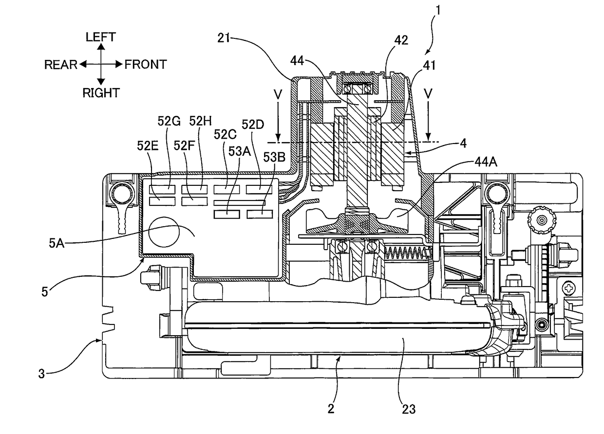
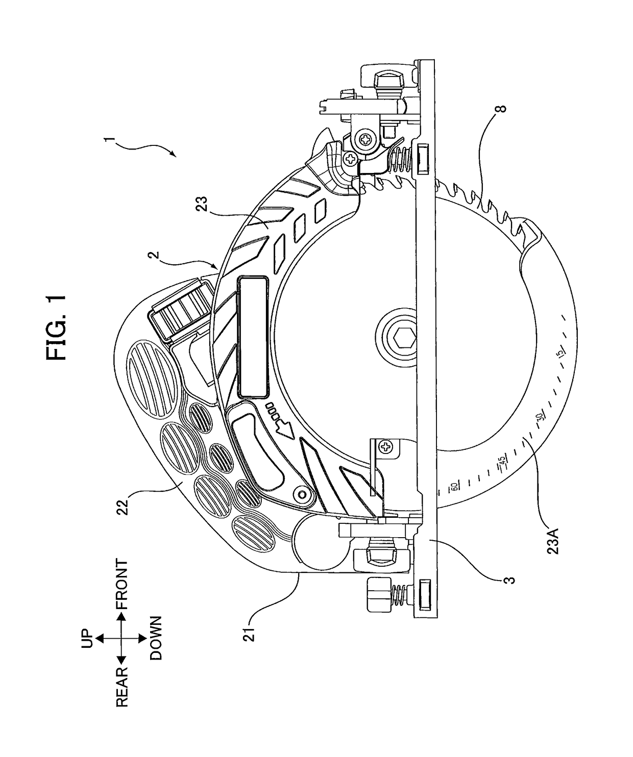
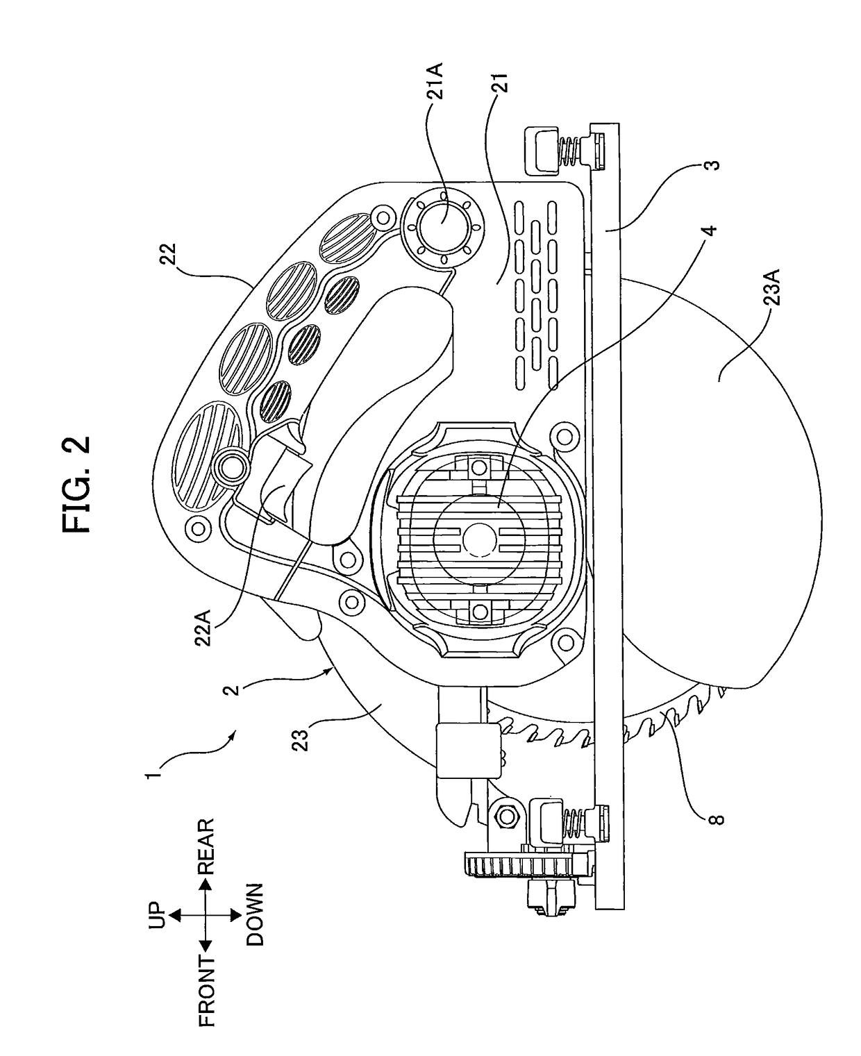
[0150]As described above, the electric circular saw 1 as an example of the power tool according to the first embodiment of the present invention is provided with the motor 4 having the stator 41 that includes star-connected three-phase windings (the U-phase winding 41U, the V-phase winding 41V, and the W-phase winding 41W), and the rotor 42 that i...

second embodiment

[0195]Thus, while drive control performed by the conventional power tool produces torque only during the period between times t2 and t5, drive control according to the present embodiment produces torque in the period between times t1 and t6, which includes and is longer than the period between times t2 and t5. In other words, when the electric circular saw 200 according to the present invention performs drive control, the period during which torque is generated is longer than the period in which torque is generated in the conventional power tool, thereby effectively suppressing torque ripple in the motor 204.

[0196]As stated above, the electric circular saw 200 as an example of the power tool according to the second embodiment of the present invention changes the number of conducting windings from three to two on the basis of the DC pulsating voltage and the induced voltage generated in the three-phase windings. In this way, the electric circular saw 200 can modify the combination of...


PUM

PropertyMeasurementUnit
capacitanceaaaaaaaaaa

Abstract

To provide a power tool capable of suppressing torque ripple and reducing power consumption without demagnetizing the permanent magnets in the rotor. The power tool includes a brushless motor, converting means, voltage detecting, and means conduction switching means. The brushless motor includes: a stator including a plurality of windings; and a rotor rotatable relative to the stator. The converting means is configured to convert an AC voltage supplied from an AC power supply into a varying DC voltage. The voltage detecting means is configured to detect the varying DC voltage. The conduction switching means includes an output line for applying the varying DC voltage to the plurality of windings. The conduction switching means is configured to perform: sequentially switching at least one winding to be applied with the varying DC voltage among the plurality of windings to rotate the rotor; and changing number of conducting windings on the basis of the varying DC voltage, the number of conducting windings being number of the at least one winding to be applied with the varying DC voltage.

Description

TECHNICAL FIELD[0001]The present invention relates to a power tool equipped with a brushless motor.BACKGROUND ART[0002]Power tools provided with a rectifier circuit for rectifying AC voltage supplied from an AC power supply, and a large-capacitance smoothing capacitor for smoothing the voltage outputted from the rectifier circuit into a substantially constant DC voltage have been widely used. Since the smoothing capacitor in this type of power tool has a large capacitance, the periods in the cycle of the AC voltage in which the absolute value of voltage from the AC power supply is higher than the voltage across the terminals of the smoothing capacitor are short and, thus, the periods in which current flows from the AC power supply to the power tool are short. Consequently, the waveform of the current flowing into the power tool from the AC power supply is distorted and has many harmonics, lowering the power factor.[0003]To resolve the problem described above, there is known in the a...

Claims


Application Information

Patent Timeline
Patent Type & Authority Applications(United States)
IPC IPC(8): H02P6/10B25F5/02H02P29/40
CPCH02P6/10B25F5/02H02P29/40B23D45/16B25F5/001B23D47/12H02P2207/05H02K7/145H02K11/33H02K11/26H02K29/03B25F5/00
Inventor IWATA, KAZUTAKAFUNABASHI, KAZUHIKO
Owner HITACHI KOKI CO LTD
Why Eureka
Try Eureka