Stator for electric rotating machine

a rotating machine and electric technology, applied in the direction of dynamo-electric machines, electrical apparatus, magnetic circuit shapes/forms/construction, etc., can solve the problems of torque ripple and deterioration of steering feeling of the driver, and achieve the effect of suppressing torque ripple of the motor, reducing the resultant magnetic flux, and preventing the distribution of magnetic flux in the motor

Active Publication Date: 2012-01-12
DENSO CORP
View PDF7 Cites 11 Cited by
  • Summary
  • Abstract
  • Description
  • Claims
  • Application Information

AI Technical Summary

Benefits of technology

[0011]With the above configuration, for each of the slots of the stator core, when the stator coil is energized so that the direction of current flowing through the in-slot portions received in the radially-outer section is the same as that of current flowing through the in-slot portions received in the radially-inner section, the directions of magnetic fields respectively created by the two currents will be opposite to each other at the corresponding connecting portion. Consequently, it is possible to reduce the resultant magnetic flux flowing through the corresponding connecting portion, thereby preventing the corresponding connecting portion from being magnetically saturated. As a result, it is possible to prevent the distribution of magnetic flux in the motor from being undesirably affected by magnetic saturation of the connecting portions of the stator core, thereby suppressing torque ripple of the motor.

Problems solved by technology

Consequently, the connecting portion 130 may be magnetically saturated, thus undesirably affecting the distribution of magnetic flux in the motor and thereby resulting in torque ripple of the motor.
As a result, when the motor is employed in an electric steering system of a motor vehicle so that the torque generated by the motor is directly transmitted to the steering wheel of the vehicle, the torque ripple will deteriorate the steering feeling of the driver.

Method used


Image

  • Stator for electric rotating machine
  • Stator for electric rotating machine
  • Stator for electric rotating machine

Examples


first embodiment

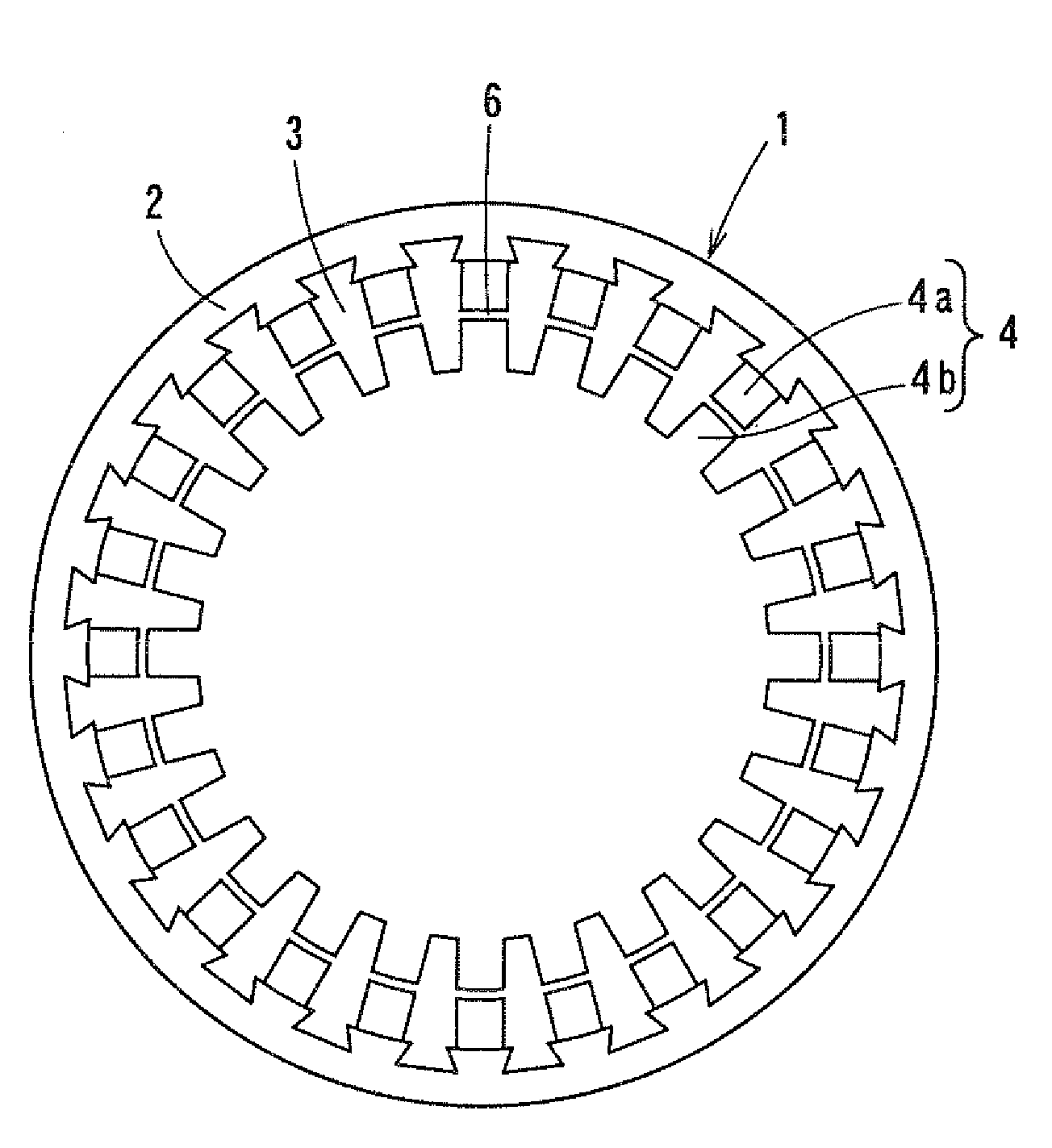
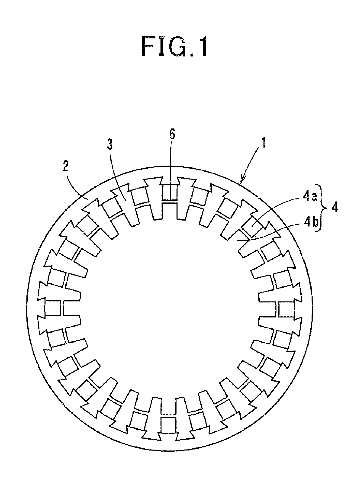
[0035]FIG. 1 shows the overall configuration of a stator core 1 of a stator according to the first embodiment of the invention. The stator is for use in an AC motor, such as an induction motor or a synchronous motor. More particularly, in the present embodiment, the stator is configured to be used in an 8-pole, 24-slot, 3-phase, full-pitch and distributed winding motor.

[0036]As shown in FIG. 1, the stator core 1 includes an annular yoke portion 2, a plurality of tooth portions 3 and a plurality of slots 4. Each of the tooth portions 3 extends radially inward from a radially inner periphery of the yoke portion 2. The tooth portions 3 are arranged at predetermined intervals in the circumferential direction of the annular yoke portion 2. Each of the slots 4 is formed between a circumferentially-adjacent pair of the tooth portions 3. In addition, in the present embodiment, both the number of the tooth portions 3 and the number of the slots 4 are set to be equal to 24.

[0037]The stator fu...

second embodiment

[0070]In the previous embodiment, the circumferential width of each of the tooth portions 3 of the stator core 1 is gradually decreased in the radially inward direction, thereby making the circumferential width of each of the slots 4 formed between the tooth portions 3 constant in the radial direction.

[0071]In comparison, referring to FIG. 7, in this embodiment, the circumferential width of each of the tooth portions 3 of the stator core 1 is set to be constant in the radial direction. Consequently, the circumferential width of each of the slots 4 formed between the tooth portions 3 is gradually decreased in the radially inward direction.

[0072]Setting the circumferential width of each of the tooth portions 3 as above, it is possible to keep the cross-sectional area of a magnetic path formed by the tooth portion 3 constant in the radial direction. As a result, it is possible to prevent each of the tooth portions 3 from being magnetically saturated.

[0073]Moreover, referring to FIG. 8,...

third embodiment

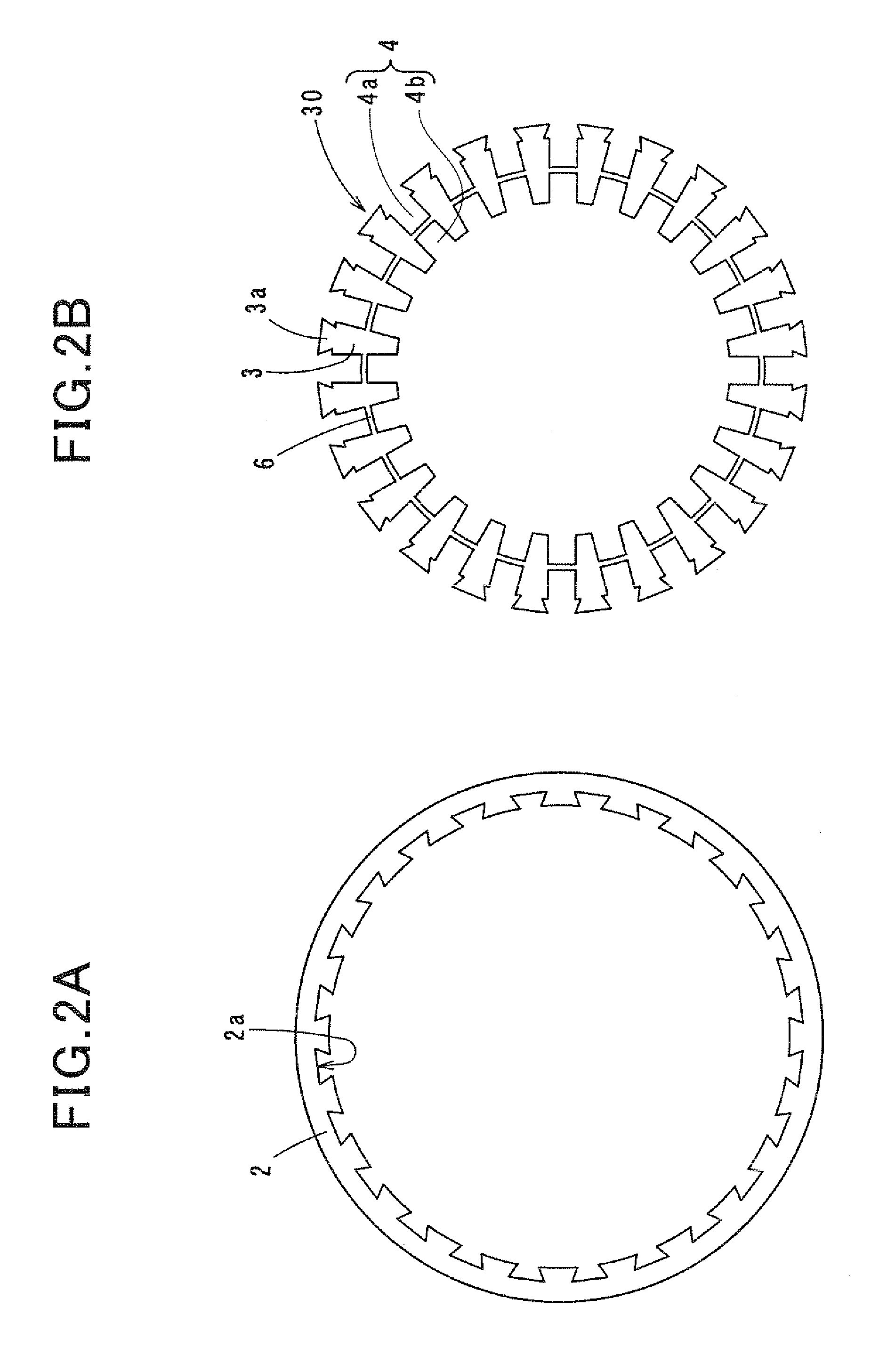
[0074]In the first embodiment, for each of the recesses 2a of the yoke portion 2 of the stator core 1, the circumferential width of the recess 2a is gradually increased in the radially outward direction. Moreover, the protrusions 3a of the tooth portions 3 are so shaped that each of the protrusions 3a can be fitted into a corresponding one of the recesses 2a of the yoke portion 2 with almost no clearance therebetween. Consequently, when viewed along the axial direction of the yoke portion 2, the recesses 2a of the yoke portion 2 and the protrusions 3a of the tooth portions 3 each have a trapezoidal shape tapering radially inward (see FIGS. 2A-2B).

[0075]In comparison, referring to FIG. 9, in this embodiment, for each of the recesses 2a of the yoke portion 2, the circumferential width of the recess 2a is set to be constant in the radial direction. Moreover, the protrusions 3a of the tooth portions 3 are so shaped that each of the protrusions 3a can be fitted into a corresponding one o...


PUM


Abstract

A stator for an electric rotating machine includes a stator core that has an annular yoke portion, a plurality of tooth portions, a plurality of connecting portions and a plurality of slots. The tooth portions are separately formed from and assembled to the yoke portion. Each of the tooth portions extends radially inward from a radially inner periphery of the yoke portion. The tooth portions are arranged in the circumferential direction of the yoke portion at predetermined intervals. Each of the connecting portions circumferentially extends to connect a corresponding circumferentially-adjacent pair of the tooth portions. Each of the slots is formed between a circumferentially-adjacent pair of the tooth portions. Moreover, each of the slots is partitioned by a corresponding one of the connecting portions into a radially-outer section and a radially-inner section.

Description

CROSS-REFERENCE TO RELATED APPLICATION[0001]This application is based on and claims priority from Japanese Patent Application No. 2010-154165, filed on Jul. 6, 2010, the content of which is hereby incorporated by reference in its entirety into this application.BACKGROUND[0002]1 Technical Field[0003]The present invention relates to stators for electric rotating machines which include a stator core having a yoke portion and a plurality of tooth portions that are separately formed from and assembled to the yoke portion.[0004]2 Description of Related Art[0005]In recent years, AC (Alternating Current) motors, such as induction motors and synchronous motors, have been required to be small in size and high in output.[0006]To meet such a requirement, there is disclosed, for example in Japanese Patent Application Publication No. H07-111746, a method of manufacturing a stator for an AC motor.[0007]Specifically, referring to FIG. 11, according to the method, a stator core 100 is configured to ...

Claims


Application Information

Patent Timeline
Patent Type & Authority Applications(United States)
IPC IPC(8): H02K1/18
CPCH02K1/165H02K2213/12H02K2213/03
Inventor TANIGUCHI, MAKOTOITO, SATOSHI
Owner DENSO CORP
Why Eureka
Try Eureka