
Long-term storage site for radioactive materials

a radioactive material and long-term storage technology, applied in the direction of nuclear elements, packaged goods, greenhouse gas reduction, etc., can solve the problems of difficult access for operators, the head of the case is oriented downwards, and it is difficult to insert the case into the transfer packag

Active Publication Date: 2014-02-25
TN INT (FR) +1
View PDF21 Cites 9 Cited by
  • Summary
  • Abstract
  • Description
  • Claims
  • Application Information

AI Technical Summary

Benefits of technology

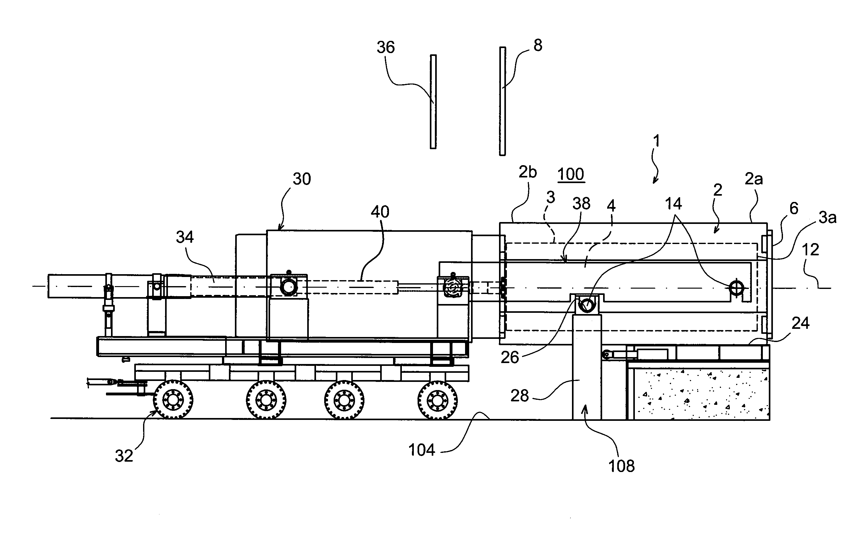
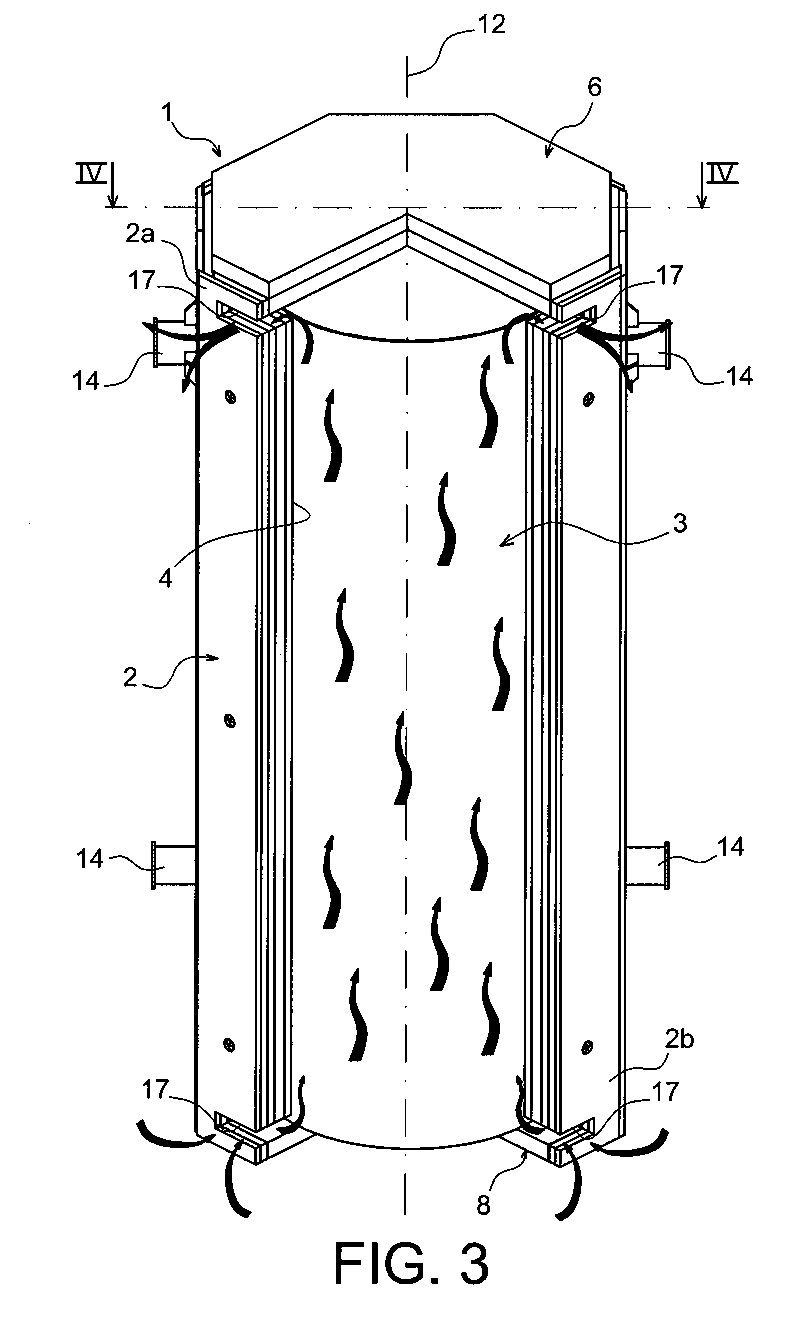
[0013]This type of removable base cover enables the insertion of the case via the low end of the package body, with the head of the case oriented to the front in the direction of movement of the case. Consequently, once transfer of the case is complete, its head is arranged at the level of the top end of the storage package, making it particularly accessible for any possible intervention for handling / checking during the long storage period.

Problems solved by technology

Since one cannot envisage turning the case over when the latter is loaded with the fuel assemblies, so that the head of the case is located at the bottom part, it is therefore impossible to insert the case into the transfer package with the head of the case oriented downwards.
The major drawback to such a system is the fact that the horizontal transfer of the case in the housing of the concrete module is done with the head of the case oriented to the front in the direction of movement of the case, such that this case top is oriented at the base of the concrete module, once transfer is complete.
Consequently, the head of the case, on which there is optionally cause to intervene during the long storage period inside the concrete module, becomes very difficult for operators to access.

Method used


Image

  • Long-term storage site for radioactive materials
  • Long-term storage site for radioactive materials
  • Long-term storage site for radioactive materials

Examples


Embodiment Construction

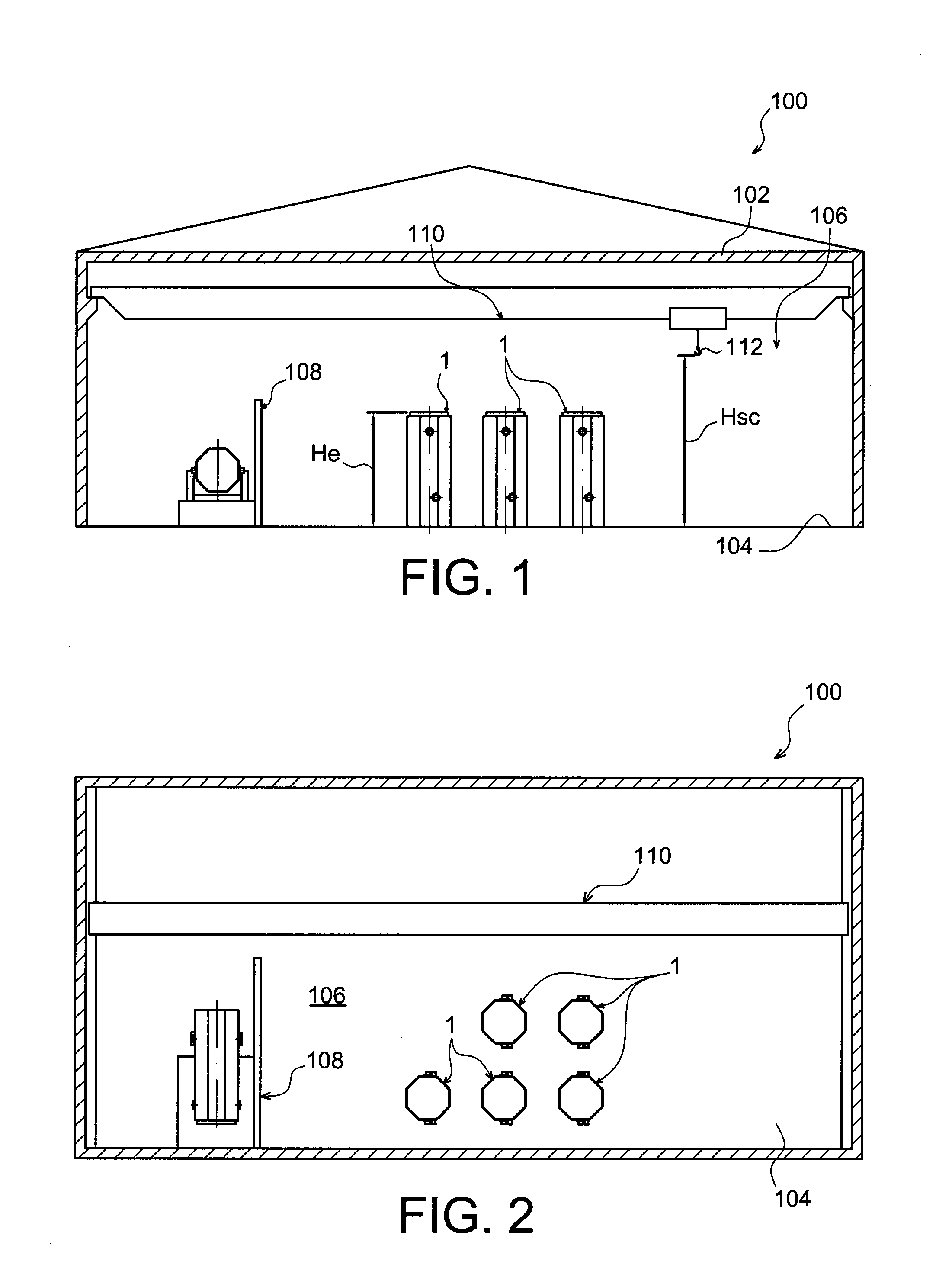
[0035]In reference first to FIGS. 1 and 2, these show a long-term storage site 100 for radioactive materials, according to a preferred embodiment of this present invention. The site 100 is closed at the top by a ceiling 102, imparting the form of a “storage facility”, in which the radioactive materials are intended to be stored over a long period of around twenty to sixty years.

[0036]The storage facility 100 has a floor or ground 104 defining a storage area on which rests vertically a plurality of elongated long-term storage packages 1, also objects of this present invention, to be detailed hereinbelow. In general, it is indicated that each of the storage packages 1 houses a case containing radioactive materials such as assemblies of irradiated nuclear fuel, the package and the case being stored in a vertical position with the removable head cover of the package and the case upper end oriented at the top, in the direction of the ceiling 102. As a guide only, the head or upper end of...


PUM


Abstract

A long-term storage facility has an array of storage packages receiving respective cases containing radioactive materials. Each storage package has a lateral body delimiting a housing for receiving a case, the package body being closed at its top end and at its low end respectively by a removable head cover, and by a package base. The package base has a removable base cover, allowing insertion of the case via the low end of the body. The packages can be moved inside the facility by a mechanical lift. The facility includes a pivoting frame for swinging a storage package from a horizontal orientation in which the storage package is loaded to a vertical position in which the storage package is stored.

Description

CROSS REFERENCE TO RELATED APPLICATIONS OR PRIORITY CLAIM[0001]This application is a national phase of International Application No. PCT / EP2008 / 058852, entitled, “CONTAINER FOR LONG-TERM STORAGE WITH REMOVABLE BASE”, which was filed on Jul. 8, 2008, and which claims priority of French Patent Application No. 07 56383, filed Jul. 10, 2007.DESCRIPTION[0002]1. Technical Field[0003]This present invention generally relates to a long-term storage package for receiving a case containing radioactive materials, such as irradiated nuclear fuel assemblies, nuclear waste, etc.[0004]The invention relates to a long-term storage site for radioactive materials, having an array of long-term storage packages each accommodating a case containing radioactive materials, and being stored in a vertical position with a removable head cover oriented upwards.[0005]The invention also relates to a transfer process for a case containing radioactive materials, from transfer package to a long-term storage package....

Claims


Application Information

Patent Timeline
Patent Type & Authority Patents(United States)
IPC IPC(8): G21C19/32G21C19/07G21F5/14G21F5/012
CPCG21F5/005G21Y2004/40G21Y2004/30G21F5/00G21Y2002/401G21C19/07G21F5/12Y02E30/30
Inventor GRUBB, ROBERT L.BONDRE, JAYANT R.WATTEZ, LISE
Owner TN INT (FR)
Learn More