Circuit protection device and protection method thereof
a protection device and circuit technology, applied in circuit devices, emergency protection circuit arrangements, electrical equipment, etc., can solve the problems of easy burn down or breakage of electronic components, affecting the other equipment,
- Summary
- Abstract
- Description
- Claims
- Application Information
AI Technical Summary
Benefits of technology
Problems solved by technology
Method used
Image
Examples
first embodiment
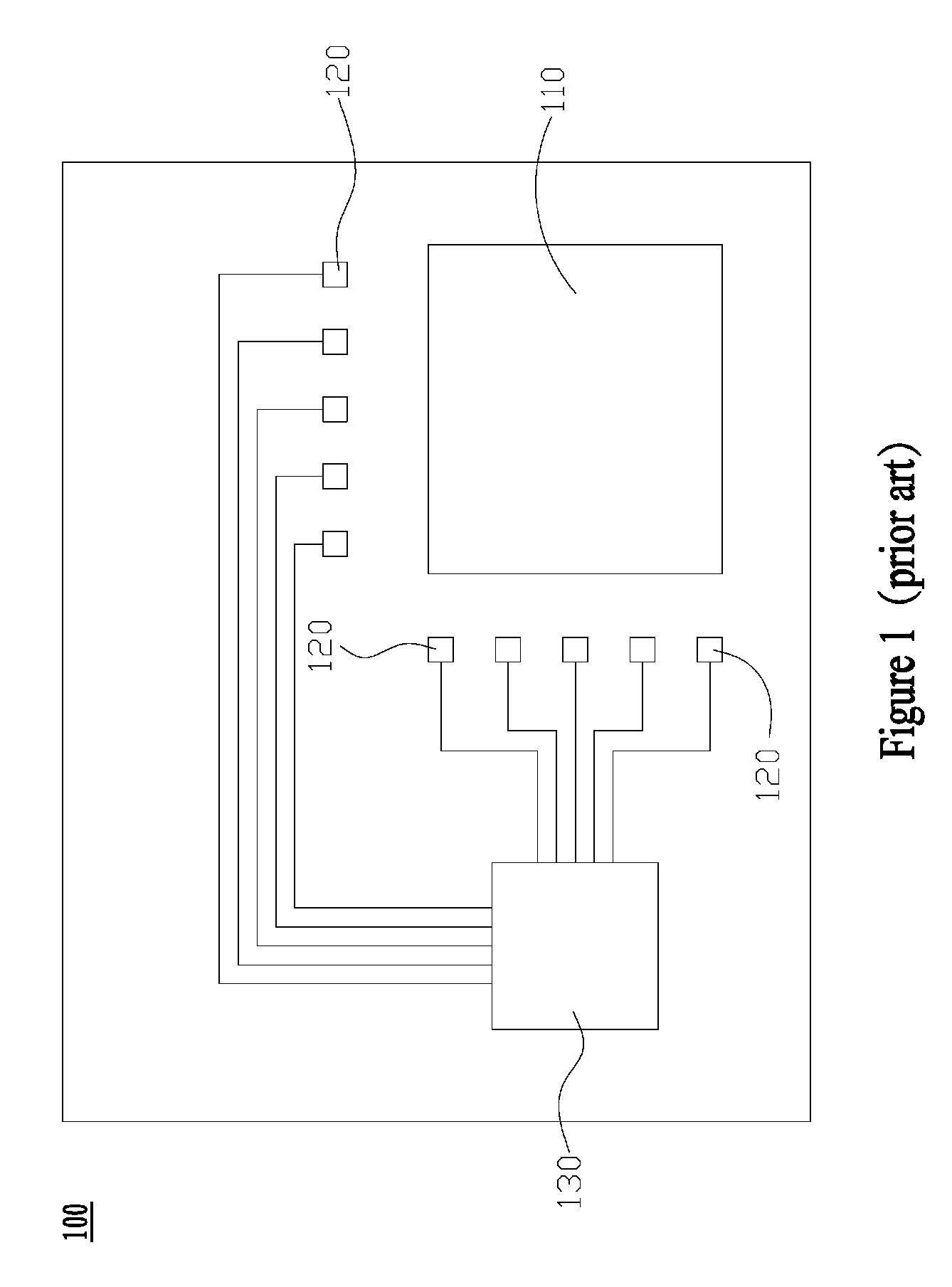
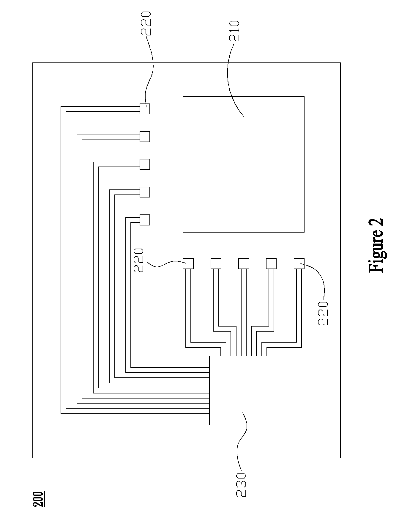
[0022]FIG. 2 illustrates the block chart of a circuit protection device of the present invention. The circuit protection device of the present invention is applicable to a circuit board 200 where a processor 210 and a plurality of transistors 220 are disposed, therefore the transistor 220 provides the current for the processor 210.
[0023]The circuit protection device of the present invention includes a Pulse Width Modulation (PWM) unit 230 electrically connecting to the plurality of transistors 220. Each transistor 220 has a current phase.
[0024]The PWM unit 230 stores a plurality of first threshold values, and each first threshold value corresponds to the transistor 220 respectively. The PWM unit 230 detects the current phase of each transistor 220 in order and judges whether the current phase of each transistor 220 exceeds the corresponding first threshold value or not. If the current phase exceeds the corresponding first threshold value, the PWM unit 230 produces a control signal t...
second embodiment
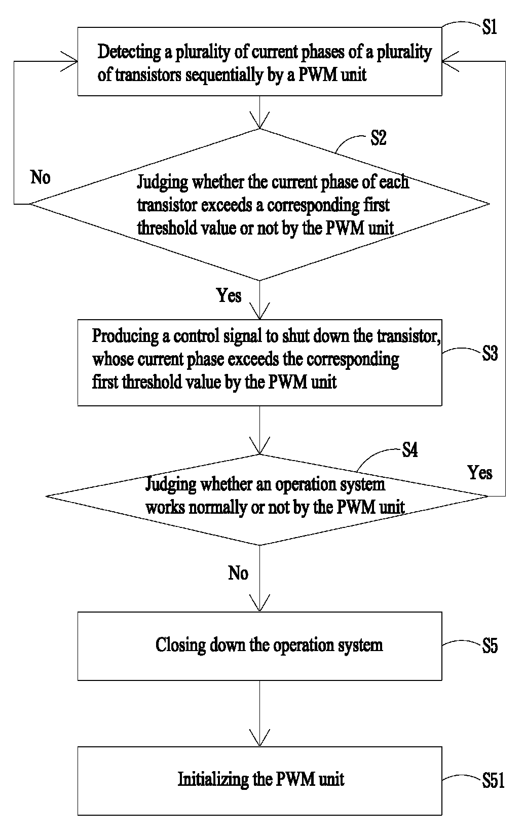
[0031]FIG. 4 illustrates the flow chart of a circuit protection method of the present invention. For the purpose to prevent the transistor 220 from being deemed as abnormal and being shut down because of the short interference of the external effects, such as Electromagnetic interference (EMI) or Electro-Static discharge (ESD), step S51 follows after shutting down the operation system. Step S51 describes the process that the PWM unit 230 initializes.
[0032]By this way, the PWM unit 230 detects all current phases of the plurality of transistors 220 anew while user reboots the operation system. The PWM unit 230 initializes to return the normal operation.
[0033]In addition, after step S4, if the operation system works normally, step S1 follows step S4; otherwise, the operation system closes down.
[0034]The PWM unit 230 of the present embodiment examines a plurality of transistors 220 repeatedly and detects each current phase again to make sure whether any abnormal transistor 220 works, th...
third embodiment
[0036]FIG. 5 illustrates the block chart of the structure of a circuit protection device of the present invention. The present embodiment features, differentiating from the former embodiment, the design further comprising a temperature sensor 240 to detect the temperature of the transistor 220. The temperature sensor 240 of the present embodiment could be a thermal resistor, but the temperature sensor 240 is not limited to that described therein.
[0037]The temperature sensor 240 electrically connects to the PWM unit 230 which stores a plurality of second threshold values. Each second threshold value corresponds to the various transistors 220 respectively.
[0038]The PWM unit 230 of the present embodiment receives the temperature information from the temperature sensor 240 and judges whether the temperature of each transistor 220 exceeds the corresponding second threshold value or not. If the temperature of the transistor 220 exceeds the corresponding second threshold value, the transis...
PUM
 Abstract
Description
Claims
Application Information
 - R&D
- Intellectual Property
- Life Sciences
- Materials
- Tech Scout
- Unparalleled Data Quality
- Higher Quality Content
- 60% Fewer Hallucinations
Browse by: Latest US Patents, China's latest patents, Technical Efficacy Thesaurus, Application Domain, Technology Topic, Popular Technical Reports.
© 2025 PatSnap. All rights reserved.Legal|Privacy policy|Modern Slavery Act Transparency Statement|Sitemap|About US| Contact US: help@patsnap.com


