Methods of meniscus repair
What is Al technical title?
Al technical title is built by PatSnap Al team. It summarizes the technical point description of the patent document.
a meniscus and joint technology, applied in the field of surgical stitching devices, can solve the problems of pain and loss of joint function, damage to surrounding articular cartilage, and early arthritis
Active Publication Date: 2014-03-04
CETERIX ORTHOPAEDICS INC
View PDF286 Cites 42 Cited by
Summary
Abstract
Description
Claims
Application Information
AI Technical Summary
This helps you quickly interpret patents by identifying the three key elements:
Problems solved by technology
Method used
Benefits of technology
The patent describes methods for repairing or reconstructing a torn meniscus of a knee using a suture passer and a suture shuttle. The methods involve positioning the suture passers around the meniscus and engaging the suture shuttle with a tissue penetrator. The tissue penetrator is then retracted and the suture shuttle is extended to repair the meniscus. The methods may be performed using continuous or non-continuous suture passers and may involve curved paths for the tissue penetrator. The technical effects of the patent include improved methods for repairing meniscus tears and the ability to access and repair the meniscus through minimally invasive procedures.
Problems solved by technology
Typically, when the meniscus is damaged, the torn piece begins to move in an abnormal fashion inside the joint, which may lead to pain and loss of function of the joint.
Early arthritis can also occur due to these tears as abnormal mechanical movement of torn meniscal tissue and the loss of the shock absorbing properties of the meniscus commonly lead to destruction of the surrounding articular cartilage.
White this may be done arthroscopically, surgical repair using a suture may be difficult because of the difficult-to-reach nature of the procedure and the difficulty in placing sutures in a way to compresses and secures the torn surfaces.
Most prior art devices for suturing or repairing the meniscus are only capable of reliably repairing vertical / longitudinal tears.
In FIGS. 63A-62C the devices affecting these repairs require projection through the meniscus and substantially into the capsule region outside of the meniscus, which could potentially damage the nearby major nerves and large blood vessels.
Further, the prior art devices, such as those placing the sutures illustrated in FIG. 63A-63C, typically place horizontal mattress suture patterns rather than vertical mattress suture patterns because vertical patterns are considerably more difficult for surgeons to place when using these devices.
Additionally, the devices forming the suture patterns illustrated in FIG. 63A-63C are only capable of point fixation; that is they cannot compress the tears uniformly across the torn surface.
Finally, such prior art devices are designed for repairing peripheral vertical meniscus tears (torn from the superior surface to the inferior surface in line with the C-shape of the meniscus) and are incapable of repairing commonly encountered radial meniscus tears.
Method used
Image
Click on the blue label to locate the original text in one second.
Reading with bidirectional positioning of images and text.
Examples
Embodiment Construction
[0103]Described herein are various embodiments of suture passers for passing a suture through tissue, and components of suture passers that particularly enhance use. In general, the suture passers described herein are continuous suture passers that are configured to pass a suture back and forth through a tissue without having to reload the device. Thus, these devices may be used for continuous stitching of tissue.
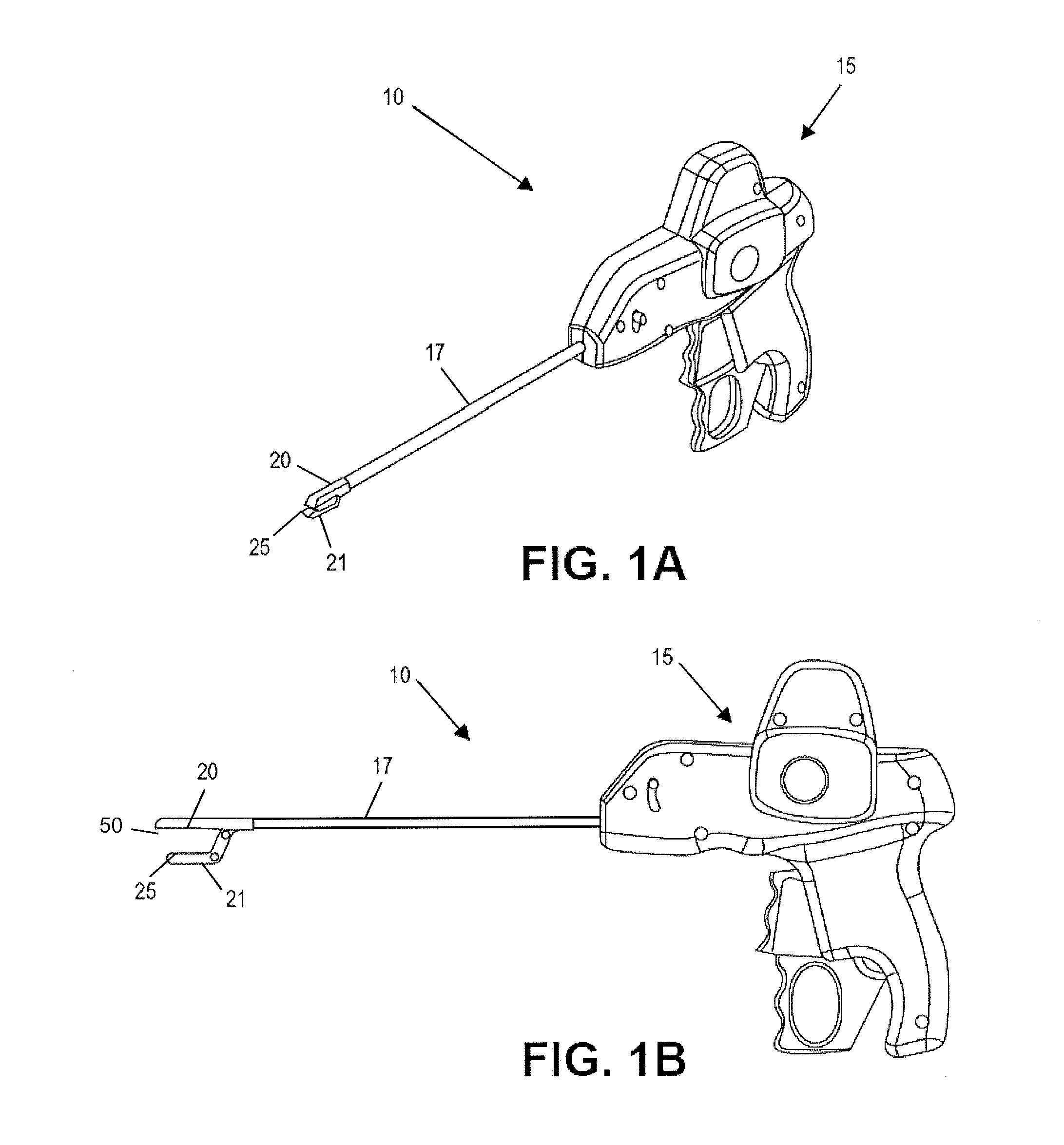
[0104]FIG. 1A illustrates a first embodiment of a continuous suture passer 10, including some of the enhanced features described herein, which may include, but is in no way limited to, a tissue penetrator (not shown), shuttle (not shown), reciprocating parallel-opening first and second jaws 20 and 21, jaw lock (not shown), and lower-jaw shuttle retainer seat 25. FIG. 1B shows a planar view of the device 10, including the parallel-opening jaws 20 and 21, tissue penetrator 50, and lower-jaw shuttle retainer seat 25.
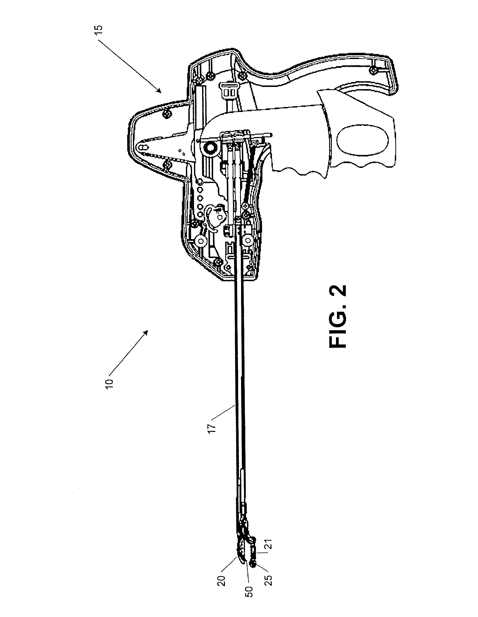
[0105]FIG. 2 illustrates a cross-sectional view of a first em...
PUM
Abstract
Methods of repairing knee meniscus tears are described which use suture passer devices and suture shuttles. These methods may be used with continuous suture passing, so that the suture passer device may remain on or in the tissue while passing a suture shuttle, and therefore a suture, back and forth from one side of the tissue to the other. These methods may be used minimally invasively for repairing meniscus tissue while avoiding further damage to the meniscus.
Description
CROSS-REFERENCE TO RELATED APPLICATIONS[0001]This application is a continuation-in-part of U.S. patent application Ser. No. 11 / 773,388, now abandoned, filed on Jul. 3, 2007, titled “METHODS AND DEVICES FOR CONTINUOUS SUTURE PASSING”.[0002]This application is also a continuation-in-part of U.S. patent application Ser. No. 12 / 291,159, filed on Nov. 5, 2008, titled “SUTURE PASSING INSTRUMENT AND METHOD” which claims the benefit of the filing dates of U.S. Provisional Patent Application Nos. 60 / 985,543, filed on Nov. 5, 2007; 60 / 985,556, filed on Nov. 5, 2007; 61 / 013,989, filed on Dec. 14, 2007; 61 / 013,994, filed on Dec. 14, 2007; 61 / 014,728, filed on Dec. 18, 2007; 61 / 013,999, filed on Dec. 14, 2007; 61 / 014,003, filed on Dec. 14, 2007; 61 / 014,012, filed on Dec. 14, 2007; 61 / 042,678, filed on Apr. 4, 2008; and 61 / 127,658, filed on May 14, 2008.[0003]This application is also a continuation-in-part of U.S. patent application Ser. No. 12 / 942,803, now U.S. Pat. No. 8,562,631, filed on Nov. ...
Claims
Application Information
Patent Timeline
Application Date:The date an application was filed.
Publication Date:The date a patent or application was officially published.
First Publication Date:The earliest publication date of a patent with the same application number.
Issue Date:Publication date of the patent grant document.
PCT Entry Date:The Entry date of PCT National Phase.
Estimated Expiry Date:The statutory expiry date of a patent right according to the Patent Law, and it is the longest term of protection that the patent right can achieve without the termination of the patent right due to other reasons(Term extension factor has been taken into account ).
Invalid Date:Actual expiry date is based on effective date or publication date of legal transaction data of invalid patent.