
Fuse assembly

a fuse assembly and assembly technology, applied in the direction of coupling device details, coupling device connections, electrical devices, etc., can solve the problems of increasing the number of electrical circuits, additional manufacturing steps and associated costs,

Active Publication Date: 2014-03-04
LITTELFUSE INC
View PDF27 Cites 11 Cited by
  • Summary
  • Abstract
  • Description
  • Claims
  • Application Information

AI Technical Summary

Benefits of technology

The patent is about a protection device for circuits. The device includes a mounting block, a fuse assembly, a post assembly, and a plug connector. The fuse assembly is made up of multiple fuses, each connected to a terminal on the mounting block. The post assembly is located inside the mounting block, with a post sticking out. The plug connector extends from one of the fuses. The technical effect of this design is that it provides a more efficient and organized way to protect circuits from damage caused by power surges.

Problems solved by technology

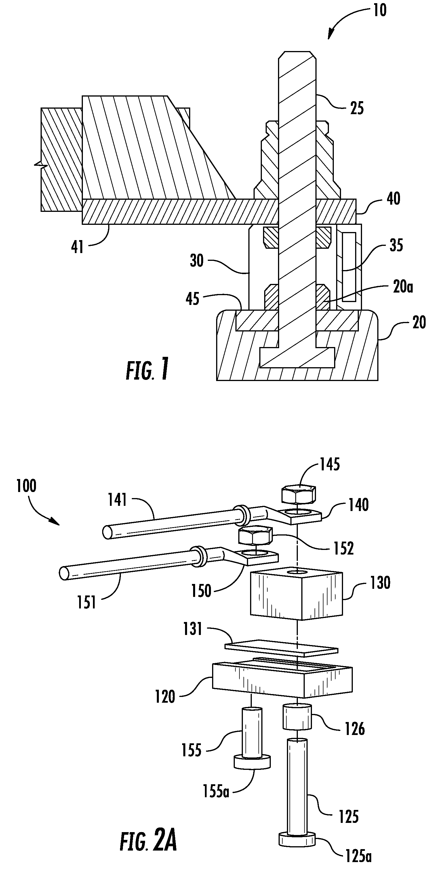
Unfortunately, by molding one end of post 25 into block 20, additional manufacturing steps and associated costs are incurred.
In addition, vehicle electrical system complexity is increasing which consequently increases the number of electrical circuits to be protected therein.
However, there is a conflicting interest to keep such protection circuits compact, light weight and easily replaceable to conserve valuable vehicle space and weight footprints.

Method used


Image

  • Fuse assembly
  • Fuse assembly
  • Fuse assembly

Examples


Embodiment Construction

[0024]The present invention will now be described more fully hereinafter with reference to the accompanying drawings, in which preferred embodiments of the invention are shown. This invention, however, may be embodied in many different forms and should not be construed as limited to the embodiments set forth herein. Rather, these embodiments are provided so that this disclosure will be thorough and complete, and will fully convey the scope of the invention to those skilled in the art. In the drawings, like numbers refer to like elements throughout.

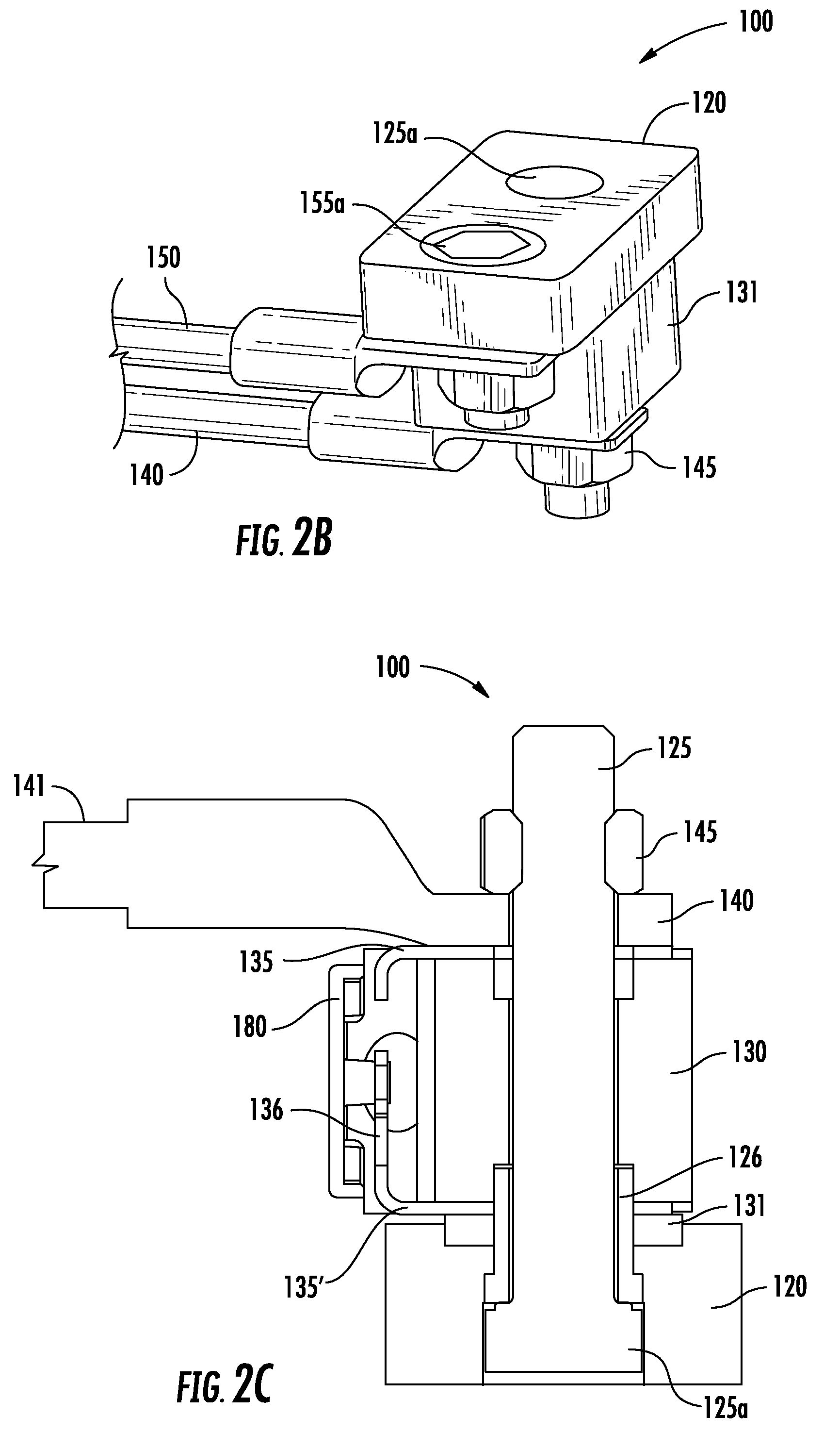
[0025]FIG. 2A is a perspective view of a fuse assembly 100 including a housing or block 120 on which one or more fuses 130 are mounted. In this illustration, one fuse 130 is shown with two posts 125 and 155 where post 155 supplies power to a bus plate 131 and post 125 receives fuse 130. In particular, first post 125 is disposed through a receiving bore in block 120 and a corresponding bore in bus plate 131. Fuse 130 may be a ceramic “block...


PUM


Abstract

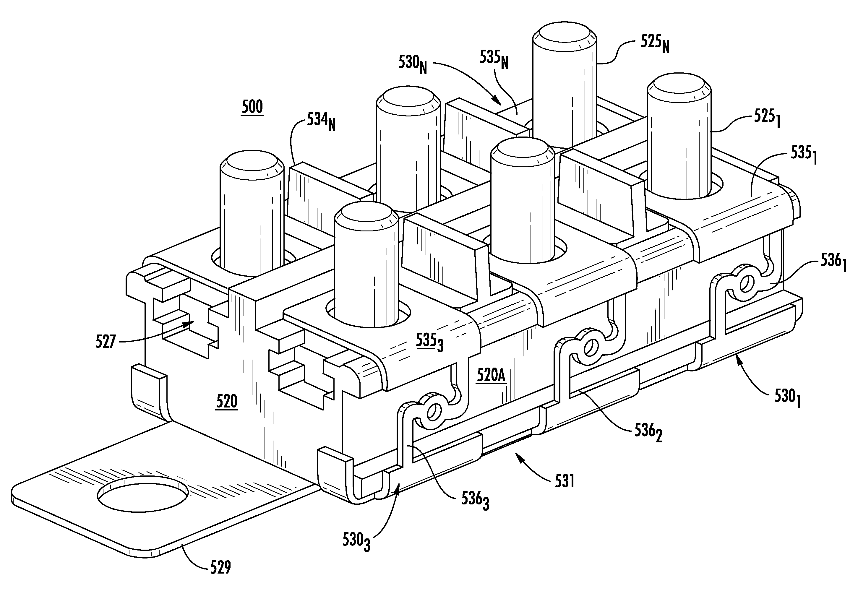
A circuit protection assembly includes a mounting block, a unitary fuse assembly, a post assembly and a plug connector. The unitary fuse assembly is disposed the mounting block and includes a plurality of fuses each of which is defined by a portion of a bus plate disposed on the lower surface of the mounting block to form a first terminal of the fuse, a second terminal disposed at least partially on the upper surface of the mounting block and a fuse element connecting the first terminal and the second terminal. The post assembly is disposed at least partially within the mounting block and a post extending from the block. The plug connector extends from a portion of the first terminal of at least one of the plurality of fuses.

Description

BACKGROUND OF THE INVENTION[0001]1. Field of the Invention[0002]Embodiments of the invention relate to the field of circuit protection devices. More particularly, the present invention relates to a fuse assembly employing a post arrangement that is easier to manufacture and provides a built-in insulating configuration with the fuse.[0003]2. Discussion of Related Art[0004]Fuses are used as circuit protection devices and form an electrical connection between a power source and a component in a circuit to be protected. In particular, a fuse may be configured to protect against damage caused by an overcurrent condition. A fuse is constructed to physically open or interrupt a circuit path and isolate electrical components from damage upon the occurrence of specified overvoltage and / or overcurrent conditions in the circuit.[0005]Electrical systems in vehicles typically include a number of these types of circuit protection devices to protect electrical circuitry, equipment, and components ...

Claims


Application Information

Patent Timeline
Patent Type & Authority Patents(United States)
IPC IPC(8): H01H85/02H01H85/165H01H85/143H01R13/68
CPCH01H85/12H01H2085/025H01H2085/0555H01R13/68H01H85/044H01H85/205
Inventor URREA, JULIOBOLD, GARY M.
Owner LITTELFUSE INC
Learn More