System for the identification of different fastening elements

a technology of fastening elements and identification systems, applied in the field of identification systems of different fastening elements, can solve the problems of easy error of fitters and often inability to carry out fittings, and achieve the effect of clear and quick

Active Publication Date: 2014-03-11
BROETJE AUTOMATION
View PDF22 Cites 1 Cited by
  • Summary
  • Abstract
  • Description
  • Claims
  • Application Information

AI Technical Summary

Benefits of technology

[0004]It is therefore an object of the invention to avoid the described disadvantage of the prior art and in particular to propose a system for the identification of different fastening elements which makes possible a clear and quick identification of differently dimensioned fastening elements from a plurality of fastening elements held in a receptacle.
[0006]The system according to the invention makes possible the simple and clear identification of an individual fastening element among a plurality of different fastening elements, which are dimensioned as a function of the components which are to be connected and are embodied as a so-called fastening element kit.
[0011]The receptacle which is held in the housing can preferably be arranged parallel to the identification elements. In particular, the housing and the receptacle can be connected with each other in a form-fitting manner. The charging of the receptacle is oriented to a charging layout which is deposited in the control arrangement of the housing. Through the skewed introduction of the receptacle into the housing, the charging layout differs from the expected charging layout, so that through the controlling of an identification element, an incorrect fastening element would be displayed. Through the form-fitting connection of housing and receptacle, an erroneously skewed insertion of the charged receptacle can be avoided.
[0012]In an advantageous further development, the receptacle can be embodied so as to be transparent on its side of the housing facing the identification elements. Thereby, the identification elements can be embodied as lighted elements such as light-emitting diodes (LED) or as incandescent lamps, in particular miniature incandescent lamps, whereby the charging positions are able to be displayed individually. In particular, in addition to the small installation space, the LEDs are distinguished by their longevity, so that the housing is frequently reusable.
[0013]The identification elements can preferably be embodied as two or more groups of diodes (LED) or incandescent lamps emitting different coloured light respectively. In this way, two or more fitters can have access in parallel to the kit arranged in the housing and can select individually the fastening elements necessary for them respectively for the connection of components.
[0014]Furthermore, the housing can have a data evaluation arrangement which evaluates a coding element arranged on the receptacle. In this way, it can be ensured that a receptacle which is charged as a kit, on its insertion into the housing, can be clearly allocated as intended to components which are to be connected with each other.

Problems solved by technology

Containers which are arbitrarily composed to form a setting case have the disadvantage that a structured depositing of fastening elements which are used for the connection of two components of a unit which is to be assembled, particularly in aircraft construction, proves to be unsuitable, when for the connection of two components a systematic choice of fastening elements which are to be used must take place by a fitter.
This is to be seen against the background that the fastening elements are dimensioned according to their use at the various connection sites of the different components, wherein an identification of the fastening element to be processed at a specific connection site of a particular component by visual differentiation of the fastening elements from each other by the fitter is very prone to error and is often not able to be carried out due to the negligible nature of the variations.

Method used


Image

  • System for the identification of different fastening elements
  • System for the identification of different fastening elements
  • System for the identification of different fastening elements

Examples


second embodiment

[0041]In FIG. 7, a receptacle 1′ for receiving fastening elements 50 is illustrated in perspective view. The receptacle 1′ is a frame 10 which is divided in its interior by a cross-piece 11 or several cross-pieces 11 into a number of compartments 12 corresponding to at least the number of different fastening elements 50 which are to be received. A container 13, embodied as a receiving element, open towards one side, for receiving identical fastening elements 50, is able to be respectively inserted into the respective compartment 12. For this, the substantially grid-shaped frame 10 has an encircling projection 14 in the respective compartments 12 on one of the two open sides, on which projection the container 13 can rest which is inserted into the compartment 12. Alternatively, the container 13 can be embodied with an encircling projection by which the container 13 can rest on the frame 10 or respectively on the cross-pieces 11 delimiting the respective compartment 12. The container ...

third embodiment

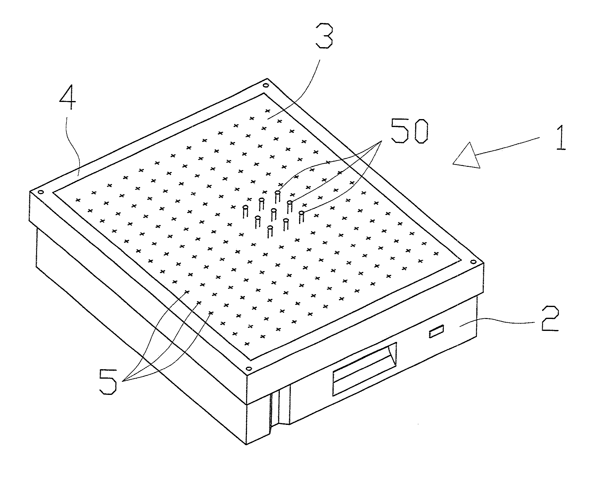
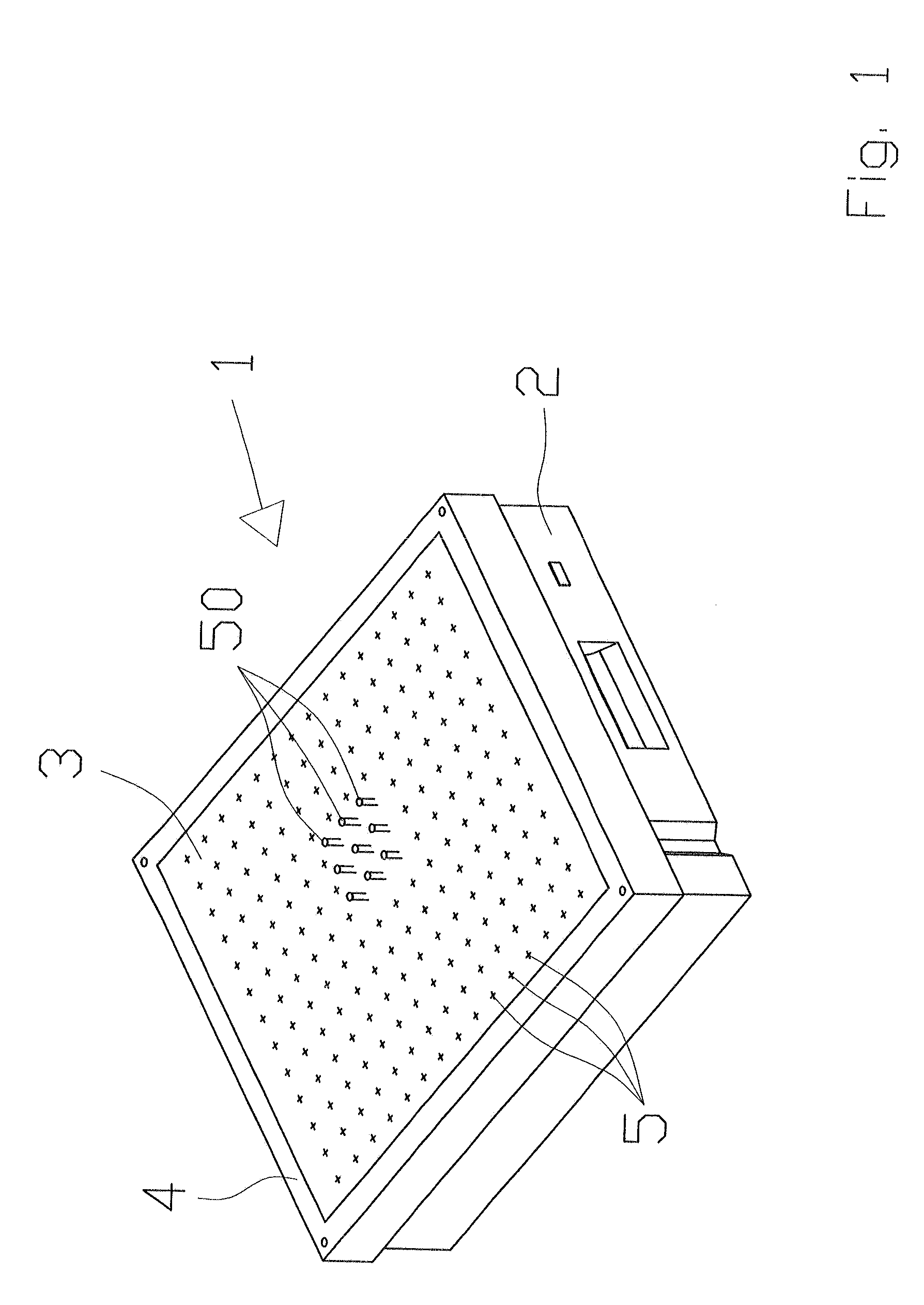
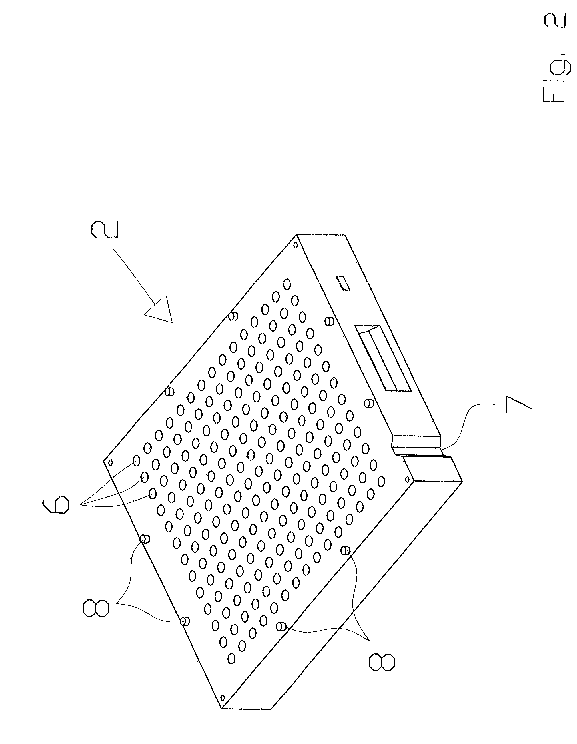
[0050]The number and the arrangement of the lighting means 33 on the bottom 32 of the housing 30 corresponds at least to the number of the openings 5 in the insert 3 of the receptacle 1 or respectively at least to the number of containers 13 or compartments 22 according to the second or third embodiment of the receptacle 1′ or 1″. Thus, for example, through the systematic activation of a single lighting means 33 by the control arrangement 35, an individual fastening element arranged in the insert 3 is able to be identified, which the fitter is to work with at a connection site on a component which is clearly identifiable by the projection system. In the case of the receptacle 1, the fastening elements 50 received by the insert 3 are illuminated directly, because respectively a fastening element, the passage 6 in the base element 2 and the associated lighting means 33 are arranged in alignment to each other. The transparent embodiment of the insert 3 makes it possible to see the ligh...


PUM


Abstract

A system for identification of different fastening elements used for connecting of components of a unit to be assembled has a receptacle to receive different fastening elements which differ from each other with regard to shape and / or size and / or material and are coordinated to the components which are respectively to be connected so that the number of fastening elements which are able to be received by the receptacle corresponds at least to the number of connection sites on the components, a housing which serves to receive the receptacle, and identification elements to display the individual charging position of a fastening element in the receptacle.

Description

CROSS-REFERENCE TO RELATED APPLICATION[0001]The invention described and claimed hereinbelow is also described in European Patent Application EP09169499.2 filed on Sep. 4, 2009. This European Patent Application, whose subject matter is incorporated here by reference, provides the basis for a claim of priority of invention under 35 U.S.C. 119(a)-(d).BACKGROUND OF THE INVENTION[0002]The invention relates to a system for the identification of different fastening elements which are used for the connecting of components of a unit which is to be assembled.[0003]Containers are known from DE 20 2004 007 880 U1 which are joined together arbitrarily for the depositing of small parts in the manner of a setting case, in which projections and recesses are arranged on the side walls of the containers, which are brought into engagement with complementary recesses or projections. Containers which are arbitrarily composed to form a setting case have the disadvantage that a structured depositing of fa...

Claims


Application Information

Patent Timeline
Patent Type & Authority Patents(United States)
IPC IPC(8): B65D90/00
CPCB65G1/1376B23P19/06
Inventor BENCZKOWSKI, KENNETHO'ROURKE, BRIANWILLER, JR., MARK A.
Owner BROETJE AUTOMATION
Why Eureka
Try Eureka