Electrical connector assembly

a technology of electrical connectors and connector assemblies, which is applied in the direction of final product manufacturing, coupling device connection, sustainable manufacturing/processing, etc., can solve the problems of limited rated (i.e. maximum) current flowing through the terminals, found in etc., to increase the maximum current, reduce the height of the electrical connector assembly, and facilitate the adhesive coating

Active Publication Date: 2014-03-18
BING XU PRECISION
View PDF56 Cites 16 Cited by
  • Summary
  • Abstract
  • Description
  • Claims
  • Application Information

AI Technical Summary

Benefits of technology

[0007]First advantages provided by the invention comprise a space is defined by the extensions of the insulating housing so that height of the electrical connector assembly can be greatly decrease to render a low profile electrical connector assembly, and enabling a person to correctly inspect the electrical connection of the FFC and a plurality of contacts of the PCB.
[0008]Second advantages provided by the invention comprise easy adhesive coating and inspection of the fastening of the adhesive when the adhesive is coated on one ends of the FFC with the plurality of contacts of the PCB exposed on the insulating housing, and the PCB fastened on a support plate of the insulating housing.
[0009]Third advantages provided by the invention comprise the second soldering holes of the PCB are electrically connected to the second contacts of the PCB, and the number of the second contacts is greater than that of the second soldering holes, thereby increasing a maximum current flowing through the second soldering holes.

Problems solved by technology

However, a couple of drawbacks have been found in the electrical connector assembly.
Second, a rated (i.e., maximum) current flowing through the terminals are limited.

Method used


Image

  • Electrical connector assembly
  • Electrical connector assembly
  • Electrical connector assembly

Examples


Embodiment Construction

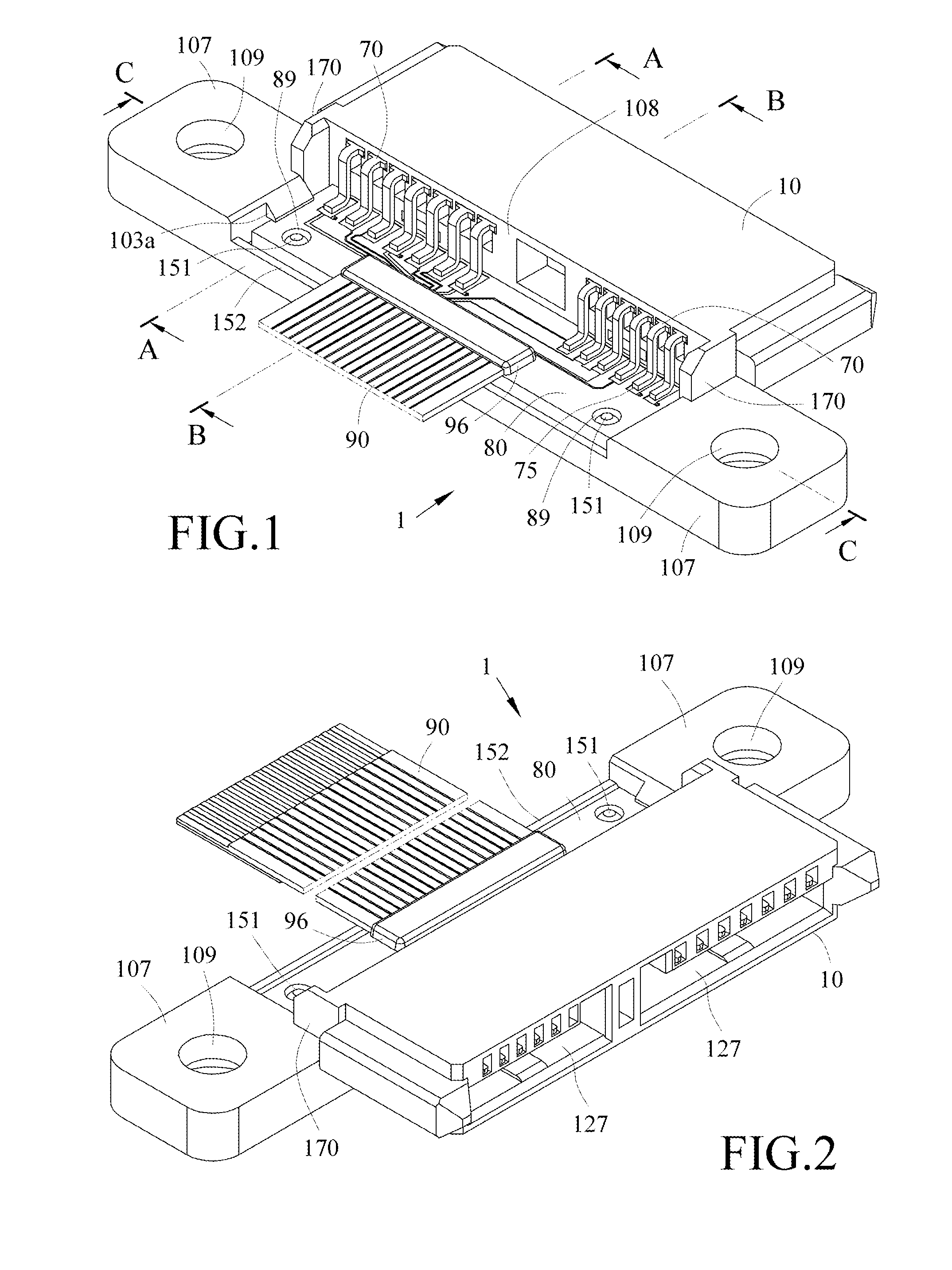
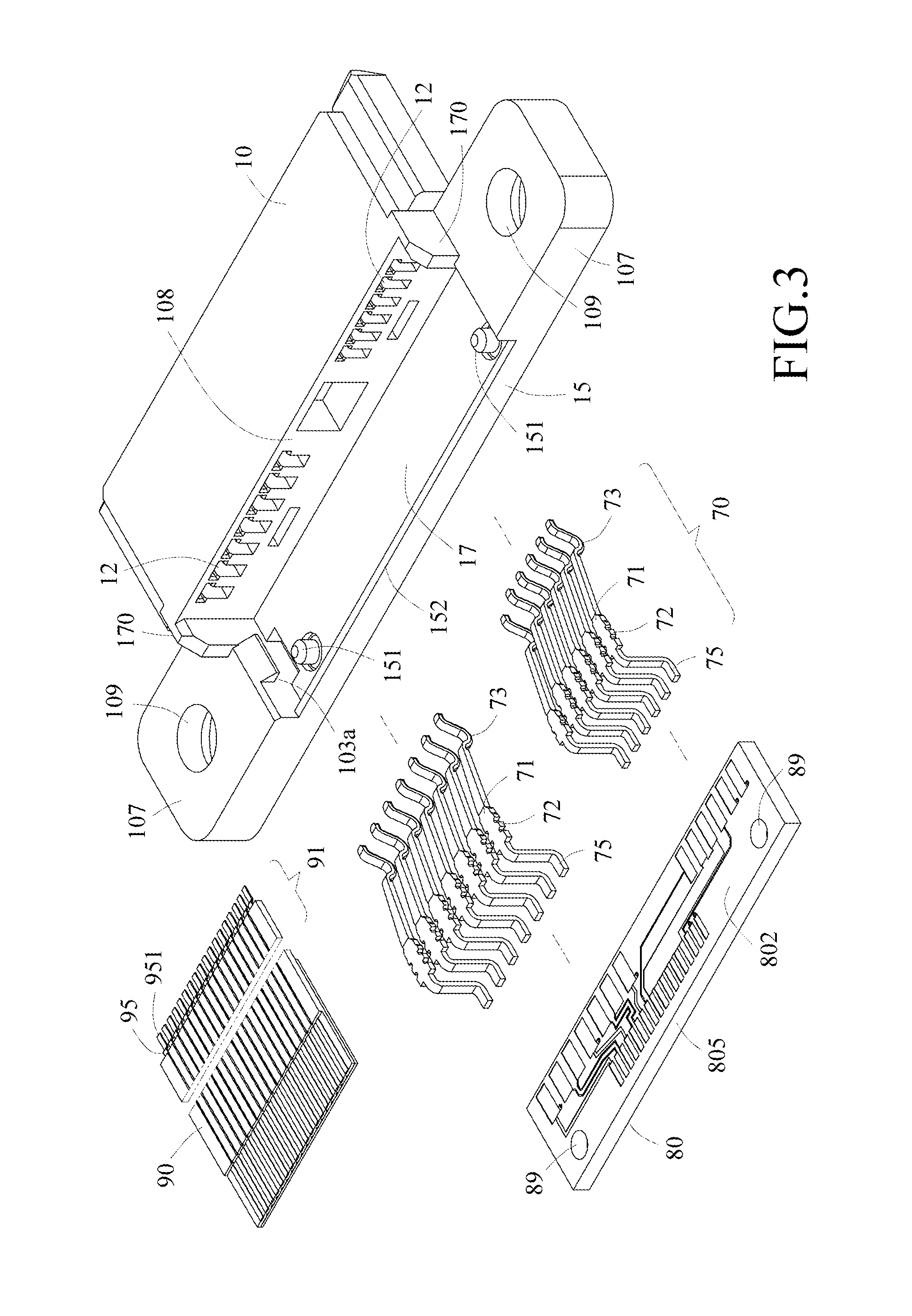
[0031]Referring to FIGS. 1 to 8, an electrical connector assembly (e.g., SATA connector) 1 in accordance with a first preferred embodiment of the invention comprises an insulating housing 10, a plurality of terminals 70, a printed circuit board (PCB) 80, and a (flex (or flexible) flat cable) FFC 90. Each component will be discussed in detail below.

[0032]The insulating housing 10 comprises a support plate 15 extending rearward out of a rear surface 108, the support plate 15 including two side pins 151 at both sides respectively, and two extensions 107 extending out of both sides of the support plate 15 respectively, each extension 107 having a vertical positioning hole 109. The PCB 80 comprises a plurality of first soldering holes 81, a plurality of second soldering holes 82, a plurality of third soldering holes 83, and a plurality of fourth soldering holes 84. The PCB 80 further comprises two side pin holes 89. In assembly, the pin holes 89 of the PCB 80 are securely put on the pins...


PUM


Abstract

An electrical connector assembly is provided with an insulating housing, a PCB, and an FFC. The insulating housing includes a plurality of terminals and two side extensions The FFC and the terminals are electrically connected together by the PCB. A plurality of contacts of the PCB are provided on a top surface of the PCB. A space is defined by the extensions and two rearward inclined members on both sides of the insulating housing respectively with each rearward inclined member joining the insulating housing and the extension. The PCB is disposed in the space.

Description

BACKGROUND OF THE INVENTION[0001]1. Field of the Invention[0002]The invention relates to electrical connectors assembly and more particularly to a SATA (Serial Advanced Technology Attachment) connector assembly including a flex flat cable, a printed circuit board, and an insulating housing having two extensions on both sides respectively, and a space defined by at least the extensions.[0003]2. Description of Related Art[0004]The disclosure of Taiwan Utility Model No. M413,241 entitled “electrical connector assembly”, filed Mar. 28, 2011, is incorporated herein by reference in its entirety. The electrical connector assembly comprises an insulating housing, a printed circuit board (PCB), and a flexible (or flex) flat cable (FFC). The insulating housing includes a plurality of terminals. The FFC and the terminals are electrically connected together by the PCB. The PCB is secured to the insulating housing.[0005]However, a couple of drawbacks have been found in the electrical connector a...

Claims


Application Information

Patent Timeline
Patent Type & Authority Patents(United States)
IPC IPC(8): H01R12/00
CPCH05K3/34H05K1/117H01R12/62H01R24/62H05K2201/1031H05K2201/0715H01R2107/00H05K2201/10356Y02P70/50
Inventor TSENG, TING, CHANG
Owner BING XU PRECISION
Why Eureka
Try Eureka