Occupant protection device
a technology for occupant protection and protection devices, which is applied in the direction of pedestrian/occupant safety arrangements, vehicular safety arrangments, vehicle components, etc., can solve problems such as difficulty in reducing impact value, and achieve the effect of improving safety
- Summary
- Abstract
- Description
- Claims
- Application Information
AI Technical Summary
Benefits of technology
Problems solved by technology
Method used
Image
Examples
embodiment 1
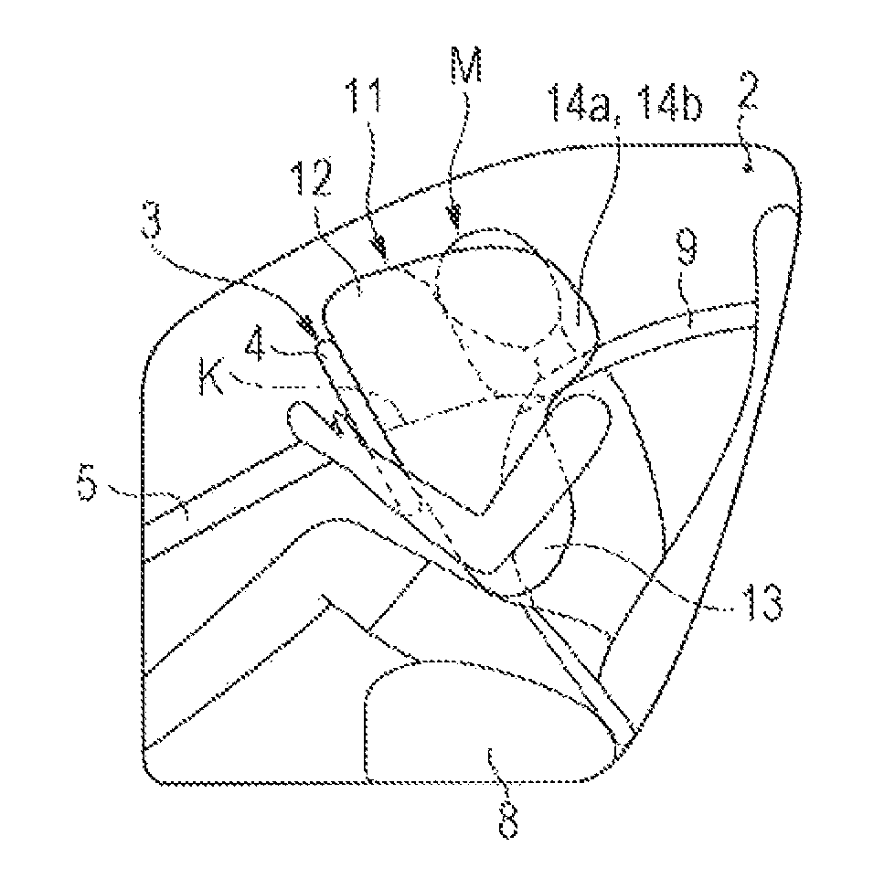
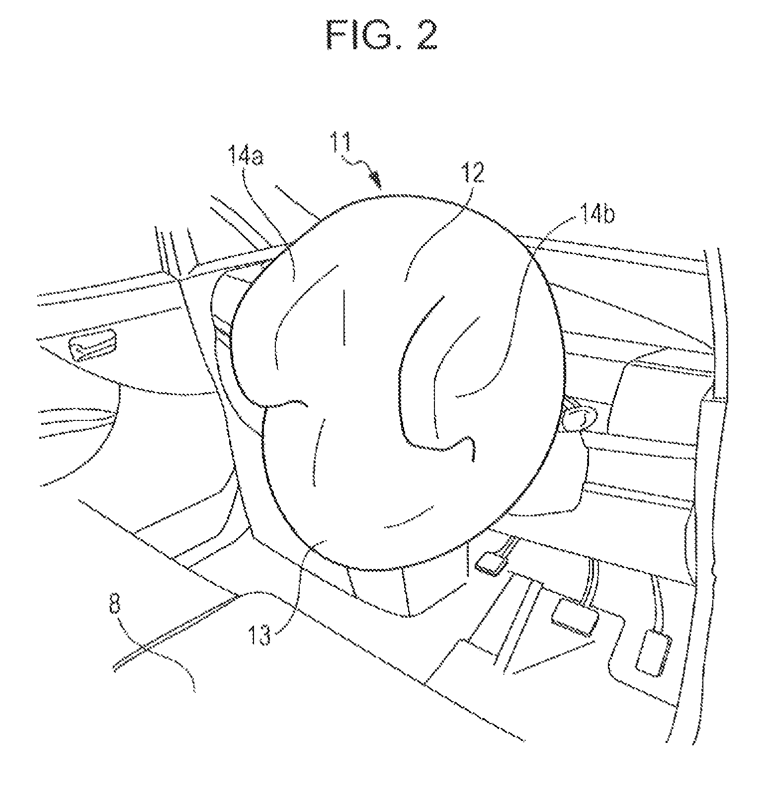
[0036]An airbag device (occupant protection device) 10 of Embodiment 1 of the present invention is stored in a center pad 7 of a steering wheel 3.
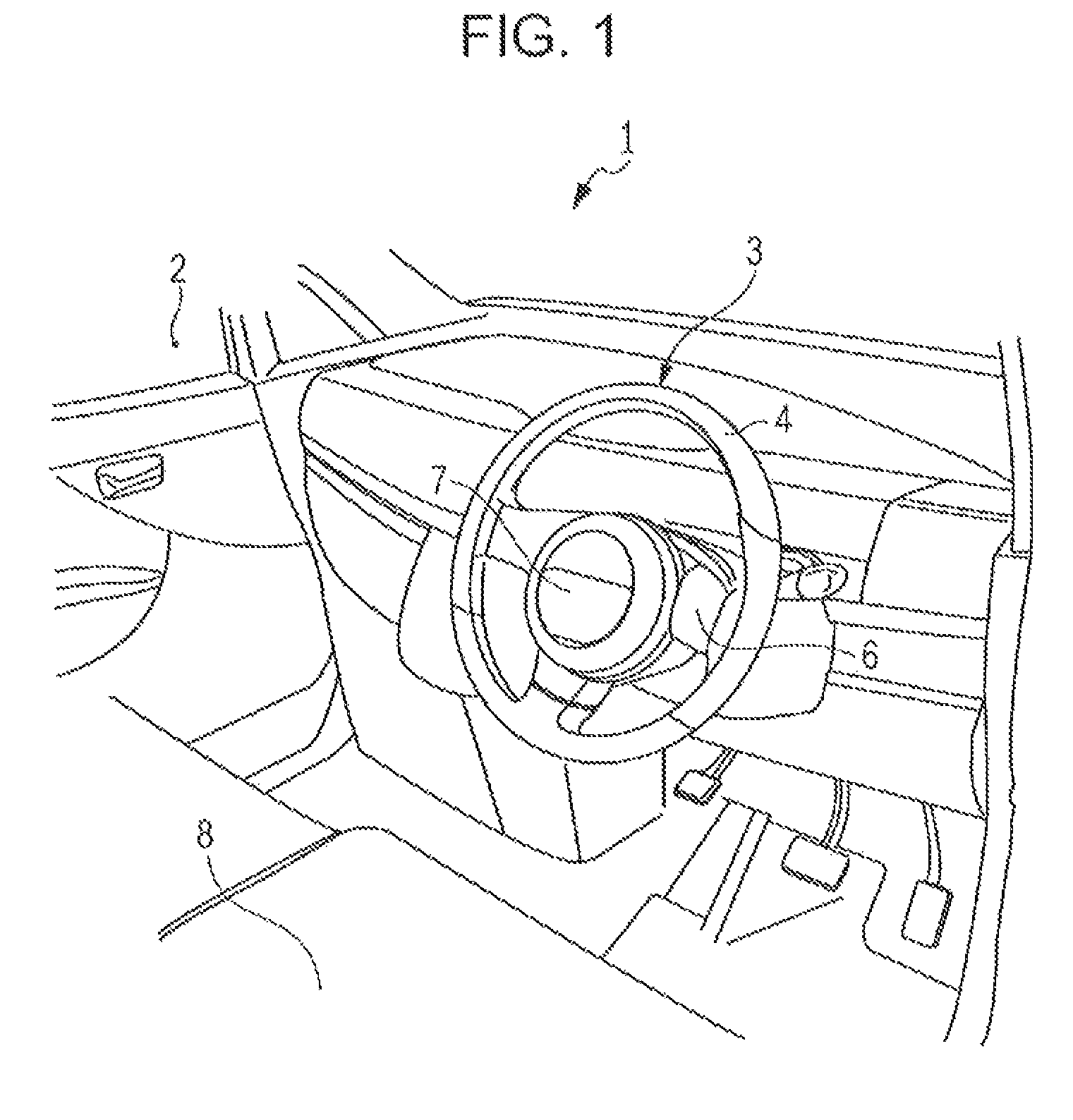
[0037]First, a description is given of the steering wheel 3 of a vehicle 1 to which the airbag device 10 of Embodiment 1 of the present invention is applied with reference to FIG. 1. FIG. 1 is a schematic view showing a cabin 2 of the vehicle 1 to which the airbag device 10 of Embodiment 1 of the present invention is applied. More specifically, FIG. 1 is a perspective view showing the cabin 2 as viewed from the rear toward the front of the vehicle 1.
[0038]As illustrated in FIG. 1, the steering wheel 3 of this embodiment includes a ring-shaped rim 4 forming an outer frame of the steering wheel 3, spokes 6 connecting the rim 4 and a steering shaft 5, and a center pad 7 provided separately from the steering shaft 5 and supported so as to have an independent non-rotating structure.
[0039]That is, the center pad 7 of this embodiment is configure...
modified example 1 of embodiment 1
[0072]Next, a description is given of Modified Example 1 of Embodiment 1 with reference to FIGS. 6 and 7. First, a description, is given of an airbag 21 of an airbag device 20 of this modified example with reference to FIG. 6. FIG. 6 is a schematic view showing a cabin 2 of a vehicle 1 to which the airbag device 20 of Modified Example 1 of Embodiment 1 of the present invention is applied. More specifically, FIG. 6 is a perspective view showing the airbag 21 of the airbag device 20 in an inflated and expanded state.
[0073]This airbag device 20 is the same as that of the above Embodiment 1 except for the shape of the airbag 21 in the inflated and expanded state. Accordingly, the elements corresponding to those of the above Embodiment 1 are referred to by the same reference numerals, and a description thereof is omitted.
[0074]As illustrated in FIG. 6, the airbag 21 of the airbag device. 20 of this modified example includes a first chamber (head protection chamber) 22 and a second chambe...
modified example 2 of embodiment 1
[0084]Next, a description is given of Modified Example 2 of Embodiment 1 with reference to FIGS. 8 and 9. First, description is given of an airbag 31 of this modified example with reference to FIG. 8. FIG. 8 is a schematic view showing a cabin 2 of a vehicle 1 to which an airbag device 30 of Modified Example 2 of Embodiment 1 of the present invention is applied. More specifically, FIG. 8 is a perspective view showing the airbag 31 of the airbag device 30 in an inflated and expanded state.
[0085]This airbag device 30 is the same as that of the above Embodiment 1 except for the shape of the airbag 31 in the inflated and expanded state. Accordingly, the elements corresponding to those of the above Embodiment 1 are referred to by the same reference numerals, and a description thereof is omitted.
[0086]As illustrated in FIG. 8, the airbag 31 of the airbag device 30 of this modified example includes a first chamber (head protection chamber) 32 and a second chamber (chest protection chamber)...
PUM
 Abstract
Description
Claims
Application Information
 - R&D
- Intellectual Property
- Life Sciences
- Materials
- Tech Scout
- Unparalleled Data Quality
- Higher Quality Content
- 60% Fewer Hallucinations
Browse by: Latest US Patents, China's latest patents, Technical Efficacy Thesaurus, Application Domain, Technology Topic, Popular Technical Reports.
© 2025 PatSnap. All rights reserved.Legal|Privacy policy|Modern Slavery Act Transparency Statement|Sitemap|About US| Contact US: help@patsnap.com


