Backlight unit and display apparatus using the same

a backlight unit and display device technology, applied in lighting and heating devices, vacuum tube vessels/containers/shields, instruments, etc., can solve the problems of low color reproduction efficiency of about 70% that of a cathode ray tube (crt), and the use of a large quantity of power, so as to increase the thickness of the reflector and increase the distance from the light source

Active Publication Date: 2014-04-01
SUZHOU LEKIN SEMICON CO LTD
View PDF29 Cites 4 Cited by
  • Summary
  • Abstract
  • Description
  • Claims
  • Application Information

AI Technical Summary

Benefits of technology

[0016]An object of the present invention is to provide a backlight unit, which includes an air guide to realize a light-weight design suited to mass-production using a reflector having an inclined surface, and a display apparatus using the backlight unit.

Problems solved by technology

The backlight units using CCFLs, however, have several disadvantages, such as consumption of a great quantity of power because power should always be applied to a CCFL, low color reproduction efficiency of about 70% that of a Cathode Ray Tube (CRT), and environmental pollution due to use of mercury.
Although LCD products using LEDs having the above described advantages have been introduced, these LCD products need expensive drivers, PCBs, etc. because LEDs have a driving mechanism different from conventional CCFLs.

Method used


Image

  • Backlight unit and display apparatus using the same
  • Backlight unit and display apparatus using the same
  • Backlight unit and display apparatus using the same

Examples


Embodiment Construction

[0058]Reference will now be made in detail to the preferred embodiments of the present invention, examples of which are illustrated in the accompanying drawings.

[0059]Prior to description of the embodiments, it will be understood that, when each element is referred to as being formed “on” or “under” the other element, it can be directly “on” or “under” the other element or be indirectly formed with intervening one or more other elements therebetween.

[0060]The terms “on” or “under” may indicate either a downward direction or an upward direction when reinforcing a single element.

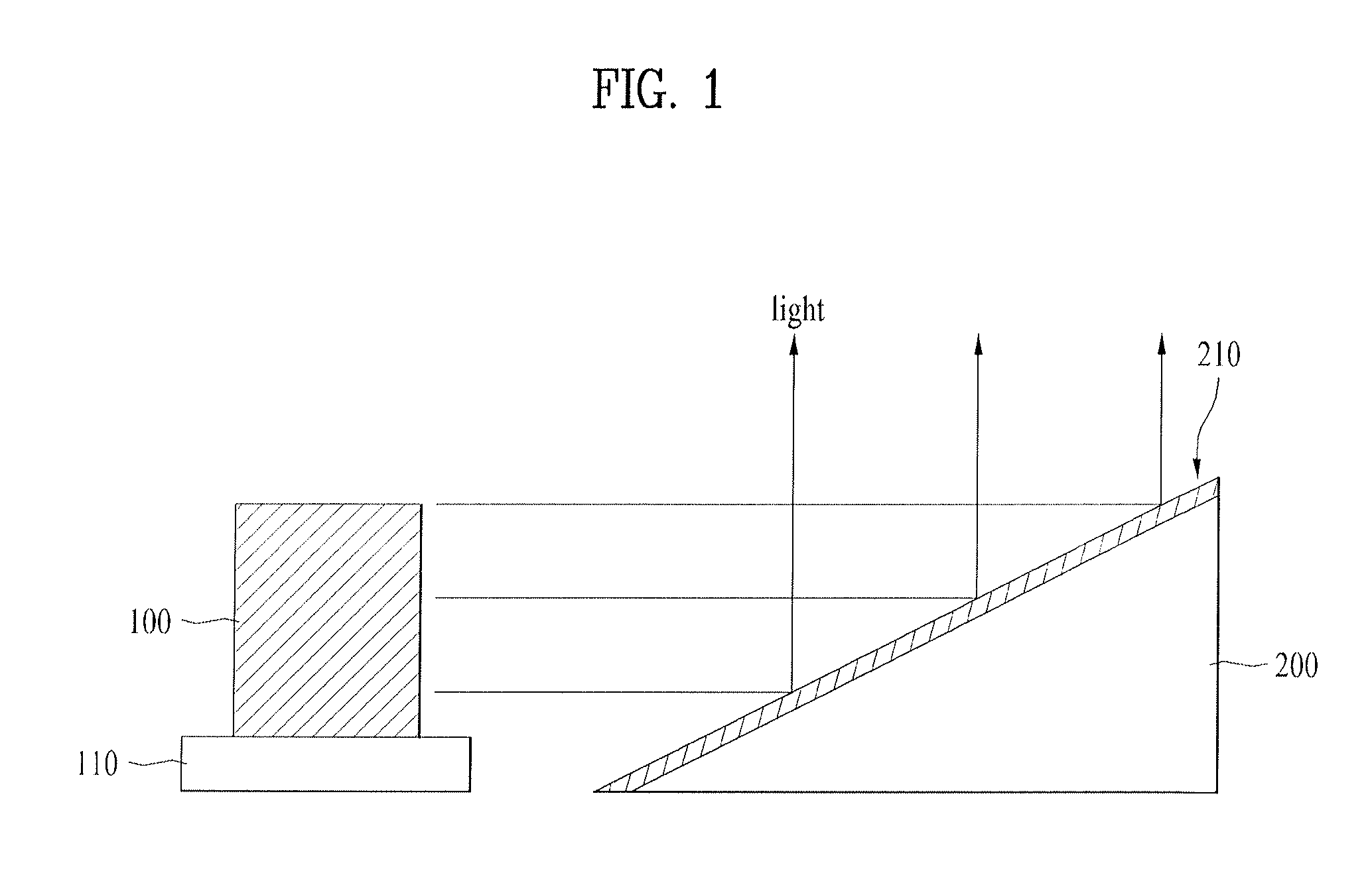
[0061]FIG. 1 is a view explaining a basic concept of a backlight unit according to an embodiment. As illustrated in FIG. 1, the backlight unit may include a light source 100 and a reflector 200. The backlight unit includes an air guide (not shown) to realize a light-weight design suited to mass-production using a reflector 200 having an inclined reflective surface 210, and a display apparatus using the backlig...


PUM


Abstract

A backlight unit and a display apparatus using the same are disclosed. The backlight unit includes an optical sheet, a reflector having a reflective surface spaced apart from the optical sheet and having an inclined surface, a fixture connected to one side of the reflector, and a light source disposed to one side of the reflector.

Description

[0001]This application claims the benefit of Korean Patent Application No. P2010-0079673, filed on, Aug. 18, 2010, and Patent Application No. P2010-0092846, filed on Sep. 24, 2010, which are hereby incorporated by reference as if fully set forth herein.BACKGROUND OF THE INVENTION[0002]1. Field of the Invention[0003]Embodiments relate to a backlight unit and a display apparatus using the same.[0004]2. Discussion of the Related Art[0005]Generally, representative large-scale display apparatuses include Liquid Crystal Displays (LCDs), Plasma display Panels (PDPs), etc.[0006]Unlike self-emission type PDPs, LCDs essentially need a separate backlight unit due to absence of self light emitting devices.[0007]Backlight units for use in LCDs are classified into edge type backlight units and vertical type backlight units according to positions of light sources. In an edge type backlight unit, light sources are arranged at left and right edges or upper and lower edges of an LCD panel and a light...

Claims


Application Information

Patent Timeline
Patent Type & Authority Patents(United States)
IPC IPC(8): F21V7/04H01J19/54
CPCG02B6/0073G02F1/133605G02F1/133615G02B6/0055G02B6/0061
Inventor KIM, MIN SANGJANG, JI WON
Owner SUZHOU LEKIN SEMICON CO LTD
Why Eureka
Try Eureka