Trick-action type clock

a technology of a timer and a rotating center, which is applied in the field of timers with a rotating center, can solve the problems of limited layout of the rotation center of the hour plate, increase in the number of components, etc., and achieve the effects of saving the power of the mechanism, simple configuration, and good appearan

Active Publication Date: 2014-04-01
RHYTHM CO LTD
View PDF9 Cites 5 Cited by
  • Summary
  • Abstract
  • Description
  • Claims
  • Application Information

AI Technical Summary

Benefits of technology

[0009]The invention proposes a trick-action type clock in which an indicator needle shaft is fixed, the trick-action type clock being capable of saving power of a mechanism with a simpler configuration and having a good appearance and an improved trick-action effect through a reasonable arrangement of a plurality of hour plates to be used.
[0014]In the second aspect of the invention, in the case of the configuration wherein in the first hour plate portion 1, the position provided with the indicator needle shaft insertion portion 1a is provided with the ring portion 1b formed in a ring shape, the third hour plate portion 3, which is rotatably provided with respect to the ring portion, is mounted on the inside of the ring portion 1b, the rotation center of the third hour plate portion 3 and the rotation center of the second hour plate portion 2 are provided at the same position (the center s), and the third hour plate portion 3 is configured to rotate coupled with the rotation of the second hour plate portion 2, the decoration is improved since the third hour plate portion 3 is further provided, and the trick-action effect may be further exhibited since the third hour plate portion 3 rotates coupled with the second hour plate portion 2.

Problems solved by technology

In particular, since the driving mechanism is disposed between the divided hour plates so as to overlap each other, the longitudinal width of the periphery of the hour plate increases in proportion to the number of the divided hour plates, and the linkage mechanism between the divided hour plates becomes complex in many respects, which inevitably causes an increase in number of components.
However, a problem arises in that a layout of the rotation center of the hour plate is limited.

Method used


Image

  • Trick-action type clock
  • Trick-action type clock
  • Trick-action type clock

Examples


Embodiment Construction

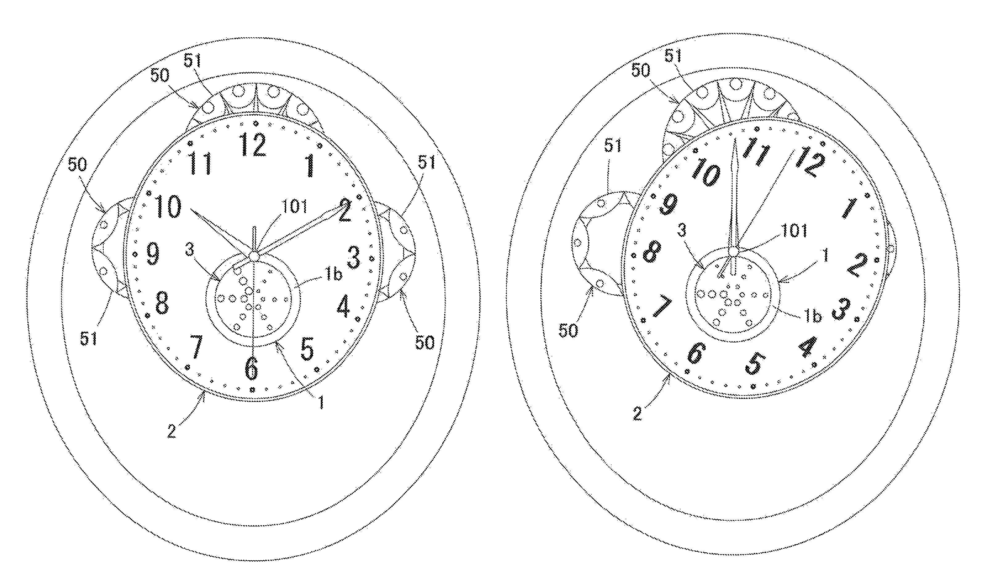
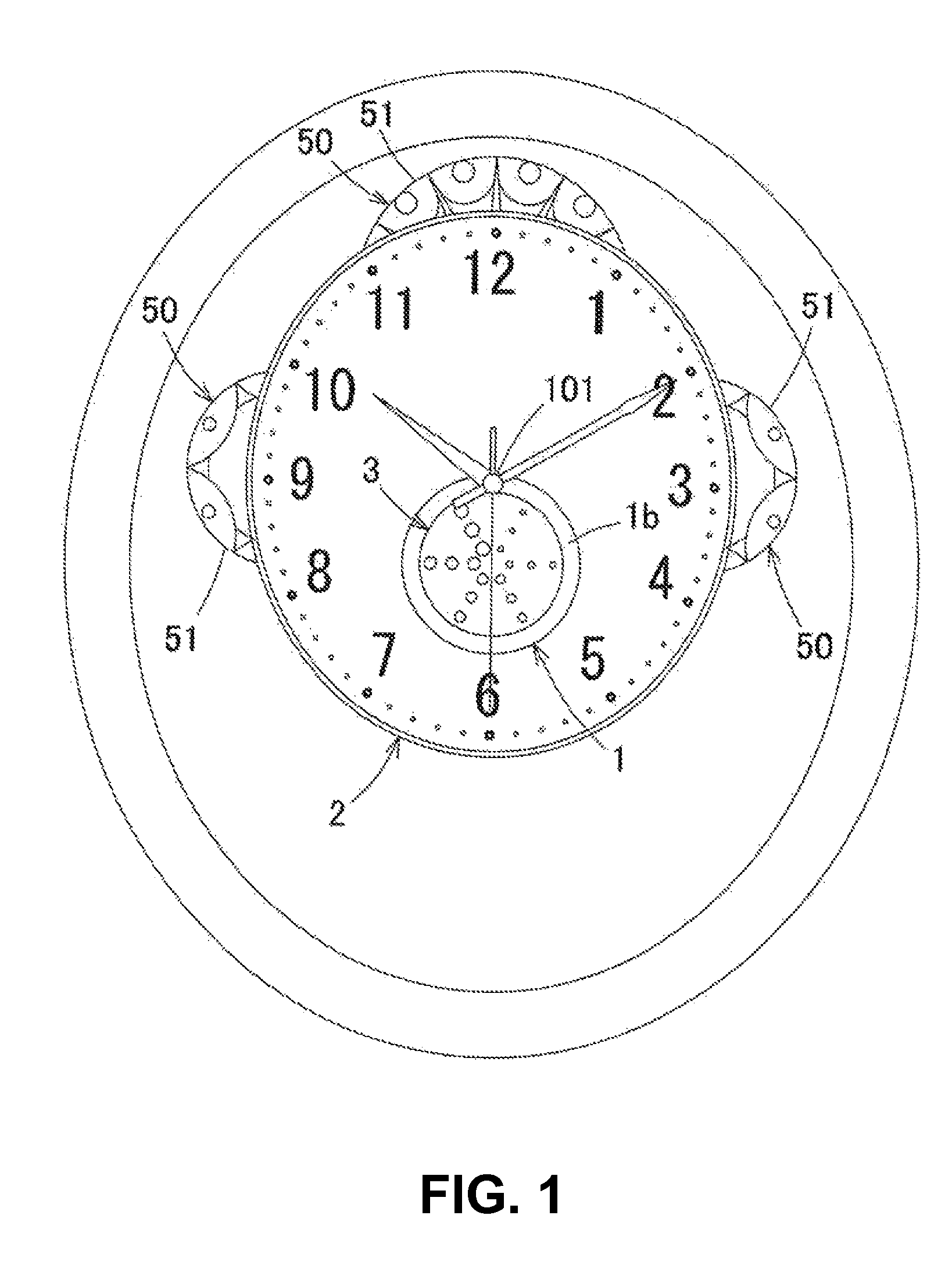
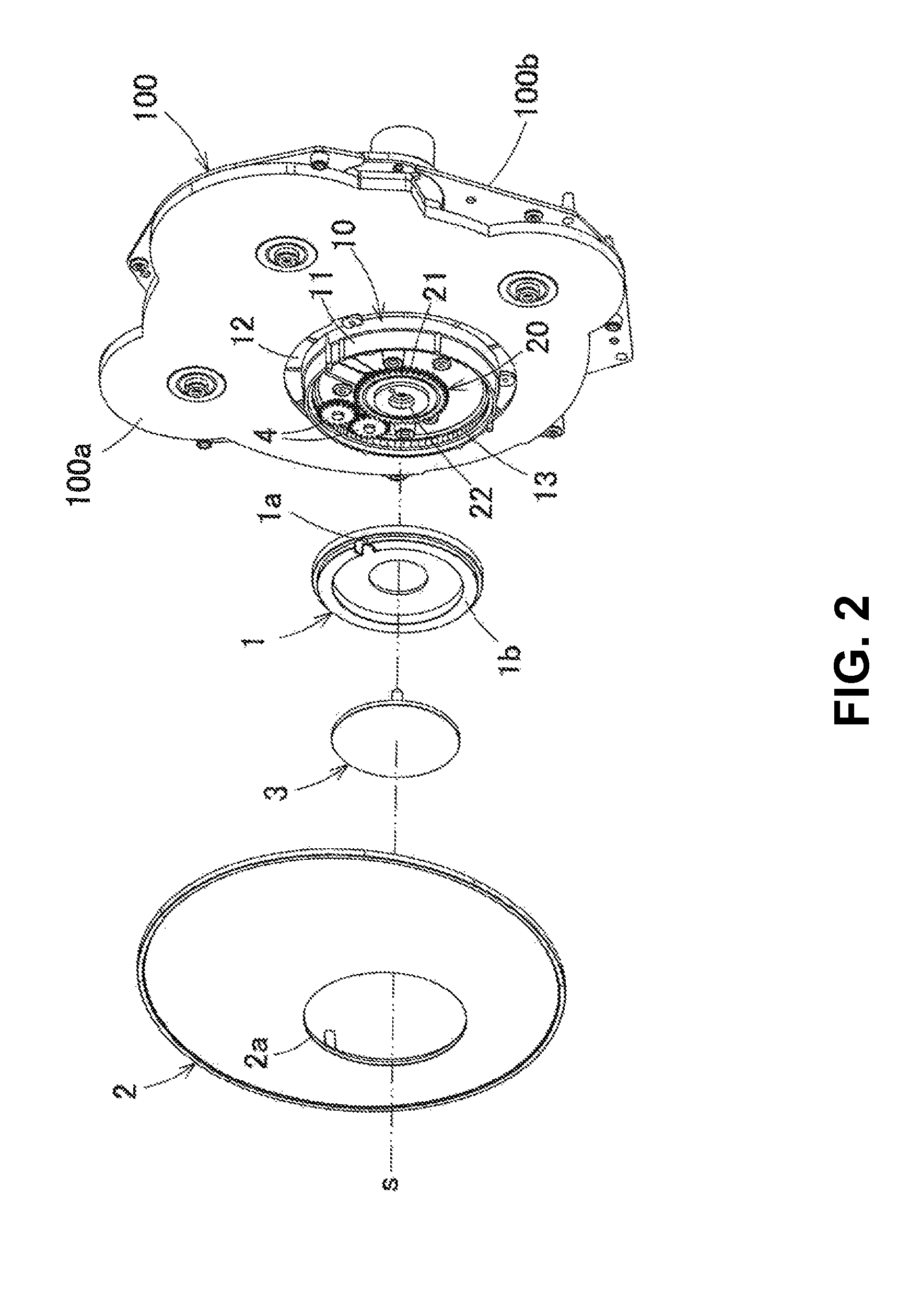
[0025]Preferred embodiments of the invention will be described below with reference to the drawings. A trick-action structure of a clock of the embodiment basically includes a first hour plate portion 1 which is fixed to a clock support plate 100 (a front support plate 100a and a rear support plate 100b) and has a circular shape (with a center s) and a second hour plate portion 2 that is rotated by a driving motor M. Furthermore, in the case of the present embodiment, a third hour plate portion 3 to be described later is separately provided, and the third hour plate portion 3 is also provided to rotate.

[0026]The first hour plate portion 1 includes an indicator needle shaft insertion portion 1a which is provided at a position remote from the center s of the first hour plate portion 1 so that an indicator needle shaft 101 is inserted therethrough. Furthermore, the first hour plate portion 1 includes, in the case of the present embodiment, a ring portion 1b which is formed in a ring sh...


PUM


Abstract

In a trick-action type clock, a part of an hour plate rotates along a plane parallel to a clock support plate. The trick-action type clock includes a first hour plate portion which is fixed to the clock support plate and has a circular shape, and a second hour plate portion which is rotated by a driving motor. The first hour plate portion includes an indicator needle shaft insertion portion which is provided at a position remote from a center of the first hour plate portion so as to insert an indicator needle shaft 101 therethrough. The second hour plate portion includes a circular notched hole which has a rotation center coincides with the center of the first hour plate portion with a circular shape and has the same shape as that of the first hour plate portion.

Description

BACKGROUND OF THE INVENTION AND RELATED ART STATEMENT[0001]The present invention relates to a trick-action type clock with a structure in which an hour plate rotates.[0002]As a conventional trick-action type clock, a clock with a rotatable hour plate is known. For this kind of trick-action type clock, for example, there is proposed a clock in which one assembled hour plate is divided into a plurality of plates every hour on the hour so as to rotate about a predetermined axis, or a clock in which a plurality of hour plates overlapping each other rotates about each axis every hour on the hour (refer to Patent Documents 1 to 3).[0003]In the trick-action type clock with the rotatable hour plate, generally, a driving mechanism is disposed between the divided hour plates so as to overlap each other and a linkage mechanism is provided between the divided hour plates so as to link them to each other.[0004]Patent Document 1: Japanese Patent Publication No. 2001-153971[0005]Patent Document 2:...

Claims


Application Information

Patent Timeline
Patent Type & Authority Patents(United States)
IPC IPC(8): G04B19/00
CPCG04B47/044G04B45/0061G04B45/00G04B19/06
Inventor NAGATAKE, KENJUMURASUGI, KOJI
Owner RHYTHM CO LTD
Why Eureka
Try Eureka