Camera module base, camera module and electronic device

A technology of camera module and packaging seat, which is applied in the direction of TV, electrical components, color TV, etc. It can solve the problems of waste of optical filters, image stains, and difficulty in realization, and achieve the effects of height reduction, cost saving, and high imaging quality

Inactive Publication Date: 2015-11-25
NANCHANG O FILM OPTICAL ELECTRONICS TECH CO LTD +3
View PDF3 Cites 3 Cited by
  • Summary
  • Abstract
  • Description
  • Claims
  • Application Information

AI Technical Summary

Problems solved by technology

[0005] In order to save costs, avoid a lot of waste of optical filters, and reduce the thickness of the camera module, some companies directly attach the optical filter 3 to the lens 2. During the focusing process, the debris produced by the resin layer will fall on the surface of the sensor chip and be directly imaged, resulting in a large number of stains on the image; if the filter 3 is attached by CSP (Chip Scale Package) technology, it will directly affect the lens. resolution, leading to a decrease in imaging quality; therefore, as far as the current technology is concerned, it is difficult to achieve

Method used


Image

  • Camera module base, camera module and electronic device
  • Camera module base, camera module and electronic device
  • Camera module base, camera module and electronic device

Examples


Embodiment 1

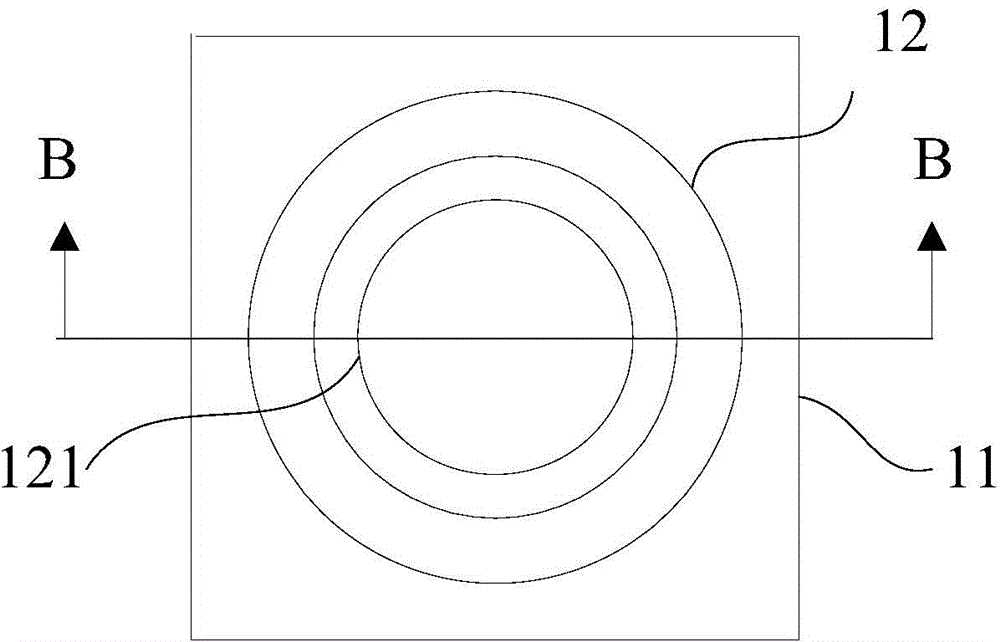
[0039] like image 3 , Figure 4 As shown, the clamping portion 121 is annular, and the outer peripheral wall of the clamping portion 121 is fixed on the inner wall of the lens barrel 12 . Simple structure and easy processing.

Embodiment 2

[0041] like Figure 5 , Figure 6 As shown, the clamping portion 121 includes at least three claws, and the claws are arranged along a circumference of the inner wall of the lens barrel 12 . The area occupied by the clamping part is small, which is beneficial for the light to be fully irradiated on the filter, and the function of the filter itself can be fully exerted, and the imaging quality is high.

[0042] On the basis of above-mentioned embodiment:

[0043] like Figure 4 , Figure 6As shown, in order to improve the stability of the camera module structure, the part of the bottom 121 a of the clamping part for contacting the optical filter 3 is located on the same plane. The surface of the filter is flat, and the larger the contact area of ​​the clamping part is, the higher the stability will be. Therefore, when the part of the bottom of the clamping part in contact with the filter is on the same plane, the contact with the filter When the surface is matched, the con...


PUM


Abstract

The invention provides a camera module base, a camera module and an electronic device. The base comprises a package base with open bottom and a barrel which is arranged on the package base. A first accommodating space which is communicated with the bottom opening is arranged in the package base. The hollow part in the barrel is communicated with the first accommodating space. The cross sectional area of the hollow part in the barrel is smaller than the cross sectional area of the first accommodating space in the package base. A clamping part which is used for clamping a filter in a second accommodating space from the edge is arranged on the inner wall of the barrel. The hollow part in the barrel is divided into two parts by the clamping part, wherein a part close to the first accommodating space is the second accommodating space. According to the invention, the filter is placed in the free space at the bottom of a lens; the thickness and the volume of the camera module base, the camera module and the electronic device are reduced; the cost of the filter is saved; and the imaging effect of the camera module is not affected.

Description

technical field [0001] The invention relates to electronic device imaging technology, in particular to a camera module base, a camera module and electronic equipment. Background technique [0002] Existing technology one [0003] The assembly structure of the existing camera module base and each component is as follows: figure 1 , figure 2 As shown, the base 1 is composed of a package seat 11 at the bottom and a lens barrel 12 at the top. The inside of the lens barrel 12 is mainly used to accommodate the lens 2, and the inside of the package seat 11 is mainly used to accommodate the optical filter 3 and the photosensitive chip 4. Finally, the flexible circuit board 5 is connected to the bottom of the package base 11, and the optical filter 3 and the photosensitive chip 4 are packaged in the package base 11. The optical filter 3 is attached to the inside of the package base 11, and is located between the lens 2 and the photosensitive chip. 4; the internal cross-sectional ...

Claims


Application Information

Patent Timeline
Patent Type & Authority Applications(China)
IPC IPC(8): H04N5/225G02B7/00G03B30/00
Inventor 梁增吉韩志良
Owner NANCHANG O FILM OPTICAL ELECTRONICS TECH CO LTD
Why Eureka
Try Eureka