
Smart machine tool lubrication system

a lubrication system and machine tool technology, applied in the field of machine tools, can solve the problems of increasing operating costs, premature wear and early failure of components, and applying too much lubricant to motion components

Active Publication Date: 2014-04-15
HAAS AUTOMATION
View PDF17 Cites 10 Cited by
  • Summary
  • Abstract
  • Description
  • Claims
  • Application Information

AI Technical Summary

Benefits of technology

The invention is a system that helps to lubricate moving parts in a CNC machine tool. It monitors the movement of the parts and uses that information to determine when to add lubricant. The amount of lubricant added can be programmed by the operator, so the system can be customized for different tools and environments. The technical effect of this invention is to improve the efficiency and lifespan of CNC machine tools by ensuring proper lubrication of moving parts.

Problems solved by technology

Applying too little lubricant to the motion components may result in the premature wear and early failure of the components.
Applying too much lubricant to the motion components increases operating costs due to the larger amounts of lubricant being applied and the extra maintenance required to remove excess lubricant from the CNC machine tool.
In addition, the excess lubricant may contaminate and / or prevent the proper operation of other parts of the CNC machine tool.
For example, excess lubricant leaked from the motion components may contaminate the cutting fluid used as coolant when shaping a workpiece.

Method used


Image

  • Smart machine tool lubrication system
  • Smart machine tool lubrication system
  • Smart machine tool lubrication system

Examples


Embodiment Construction

[0017]The detailed description set forth below in connection with the associated drawings is intended as a description of various embodiments of the invention and is not intended to represent the only embodiments in which the invention may be practiced. The detailed description includes specific details for the purpose of providing a thorough understanding of the invention. However, it will be apparent to those skilled in the art that the invention may be practiced without all of the specific details contained herein. In some instances, well known structures and components are described in general and may be shown in block diagram form in order to avoid obscuring the concepts of the invention.

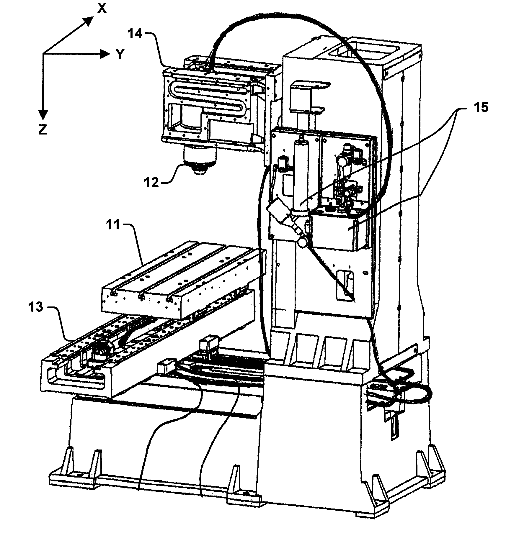
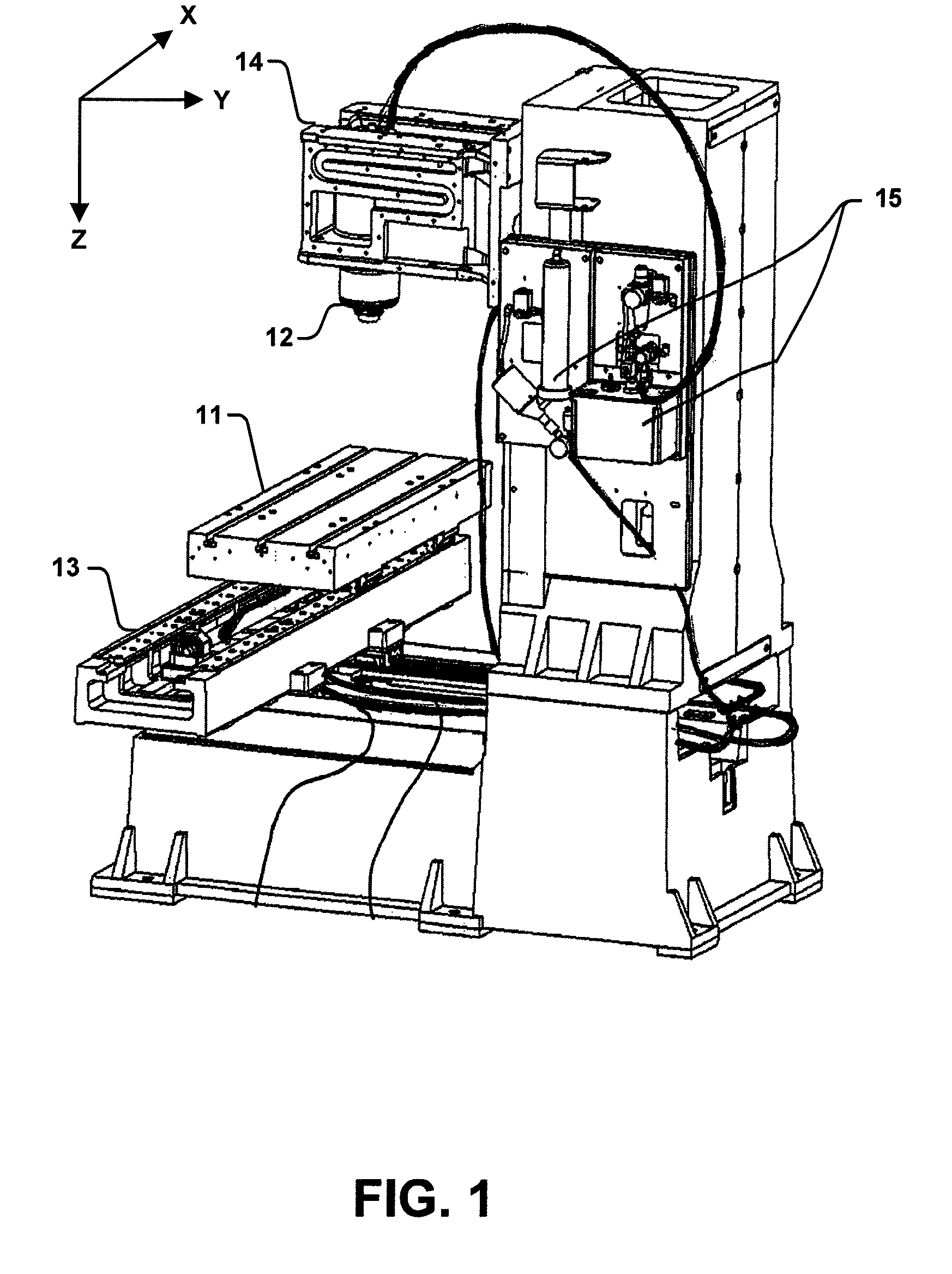
[0018]FIG. 1 is a perspective drawing of portions of a machine tool 10 that will be referenced to describe the operation of various embodiments of a machine tool lubrication system. Machine tool 10 includes a table 11 and a spindle 12. Table 11 is configured to temporarily hold a workpiece (not...


PUM


Abstract

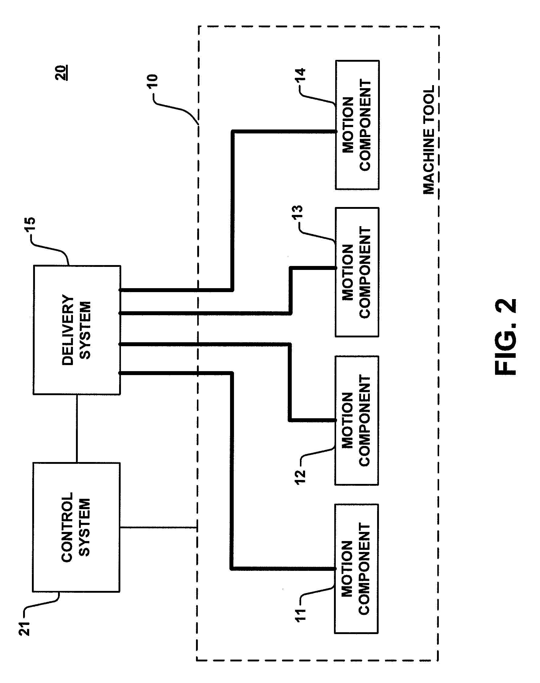
A smart machine tool lubrication system monitors the distance traveled by a motion component in a machine tool. A predetermined amount of lubricant is dispensed at a lubrication point of the motion component when the monitored distance exceeds a first threshold value. The smart machine tool lubrication system may further monitor the duration of time the motion component is in motion and dispense the predetermined amount of lubricant with the monitored duration of time exceeds a second threshold value.

Description

[0001]This application claims the benefit of U.S. Provisional Application No. 61 / 039,742, filed Mar. 26, 2008, which is hereby incorporated by reference herein.FIELD[0002]The invention relates to machine tools and, in particular, concerns a smart lubrication system for lubricating the motion components of a machine tool.BACKGROUND[0003]Machine tools allow an operator to fabricate products by shaping a workpiece using one or more cutting tools. Computer numerical control (“CNC”) machine tools automate the fabrication process by controlling the relative positions of the workpiece and the cutting tools, as well as the operation of the cutting tools, in accordance with instruction sequences in user programs. In this manner, CNC machine tools are capable of fabricating multiple instances of the same product with little or no variation between the products. CNC machine tools use a number of movable or motion components to position both the workpiece and the cutting tools during the fabric...

Claims


Application Information

Patent Timeline
Patent Type & Authority Patents(United States)
IPC IPC(8): F16N27/00
CPCB23Q11/125B23Q11/123B23Q11/124G05B2219/49043G05B19/18
Inventor HAAS, GENE F.ZIERHUT, KURT P.TEITEL, MICHAEL A.
Owner HAAS AUTOMATION
Learn More