Delivery system, method, and anchor for medical implant placement

a technology of medical implants and delivery systems, applied in the field of medical implants, to achieve the effect of convenient adaptation and configuration

Active Publication Date: 2014-04-15
UIM PRESSURE IMPLANT INC
View PDF22 Cites 26 Cited by
  • Summary
  • Abstract
  • Description
  • Claims
  • Application Information

AI Technical Summary

Benefits of technology

[0009]A technical effect of the invention is the ability to provide a reliable anchor for securing a medical implant within the human body, and a procedure for placing a variety of implantable medical devices, including those adapted to monitor physiological parameters including pressures within the heart. The anchor can be readily adapted and configured to address delivery issues, including delivery method, delivery equipment, implant design, and anchor location, that arise when employing chronically implanted physiologic devices, sensors, and actuators, particularly if used to diagnose, monitor and / or treat cardiovascular diseases such as CHF and CHD. Notably, the anchor and its delivery find application in the very challenging application of monitoring the pressure of the left side of the heart. Medical implants that can be placed and anchored in accordance with this invention can operate wirelessly or can be connected to other devices (such as pacemakers) using electrical wires (e.g., pacemaker leads, polymer based flex cables, or wires) or other types of communications means (e.g., ultrasonic, optical, or electrophysiology signals).
[0010]Other aspects and advantages of this invention will be better appreciated from the following detailed description.

Problems solved by technology

Notably, the anchor and its delivery find application in the very challenging application of monitoring the pressure of the left side of the heart.

Method used


Image

  • Delivery system, method, and anchor for medical implant placement
  • Delivery system, method, and anchor for medical implant placement
  • Delivery system, method, and anchor for medical implant placement

Examples


Embodiment Construction

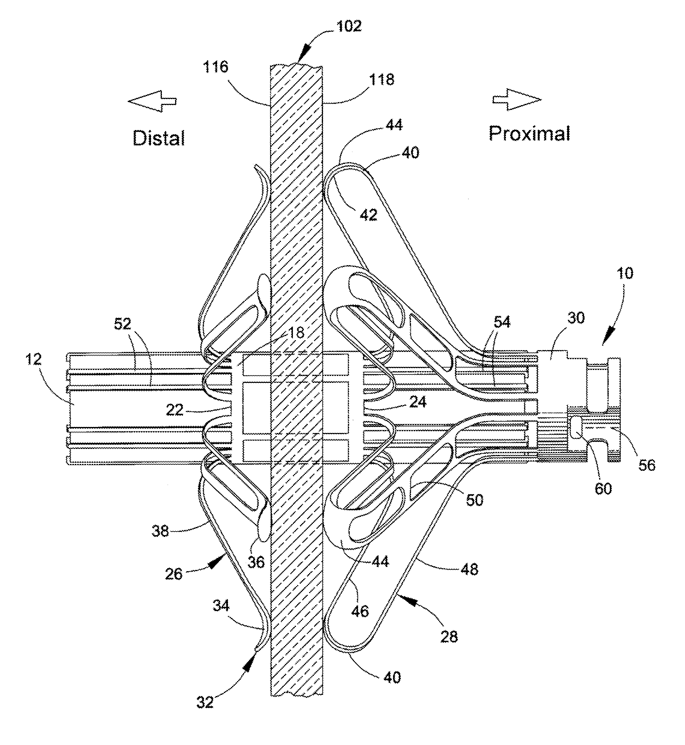
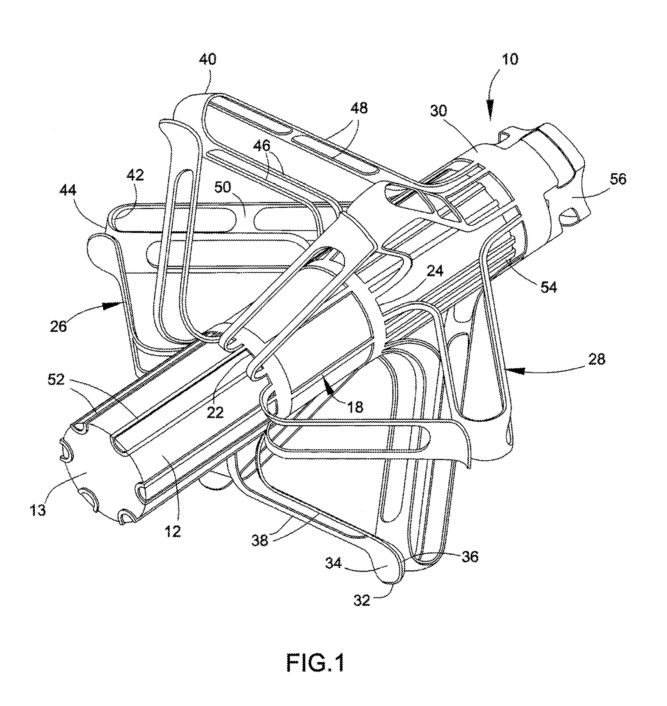
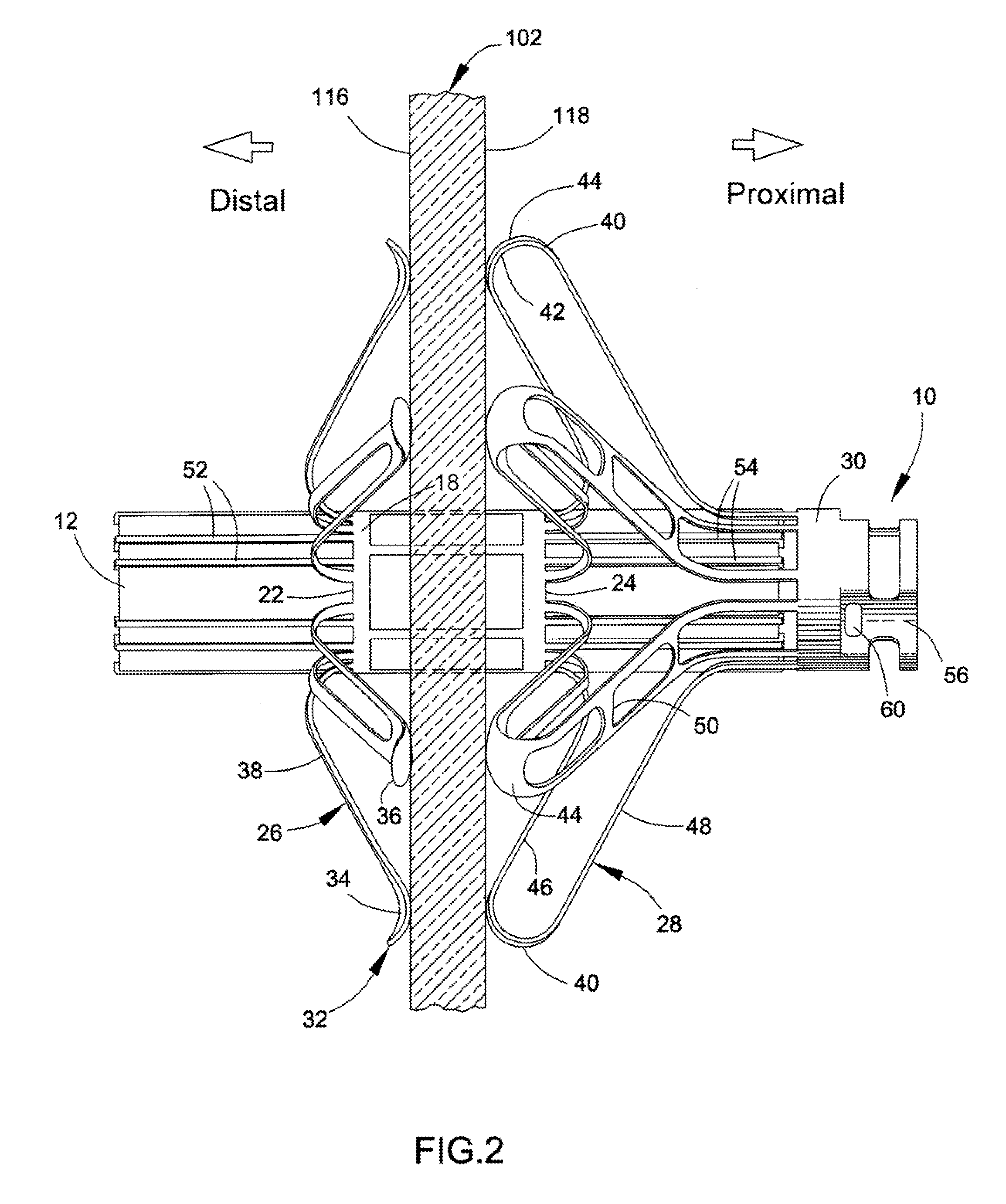
[0018]FIGS. 1 through 8 depict an anchor 10 and a delivery system 100 suitable for delivering and securing a medical implant 12 to a wall 102, such as a wall 102 of an internal organ (FIGS. 2 and 3), in accordance with an embodiment of the present invention. As a notable example, the wall 102 can be an atrial septum and the implant 12 can be employed to measure physiological parameters of the heart, such as LVEDP or MLA pressure. The implant 12 may be any one of a variety of types of implants currently known or developed in the future, and the scope of the present invention is not limited in any way by the type and operation of the implant 12. Implantable devices capable of being delivered with the present invention include but are not limited to wireless implants disclosed in commonly-assigned U.S. Pat. Nos. 6,926,670, 6,968,743, 7,211,048, 7,615,010 and 7,686,762 and U.S. Published Patent Application Nos. 2006 / 0047205, 2007 / 0032734, 2008 / 0077016, 2008 / 0269573, 2009 / 0005656, 2009 / 0...


PUM


Abstract

An anchor for a medical implant, methods of manufacturing the anchor, and procedures for placing a medical implant, such as for diagnosing, monitoring and / or treating cardiovascular diseases. The anchor has a base portion with first and second longitudinal ends and a cage therebetween. The anchor further has flexible arms, flexible legs, features for securing the medical implant within the cage of the base portion, and a coupler portion connected to and spaced apart from the second longitudinal end of the base portion. The anchor is adapted to have a deployed configuration in which the arms and legs radially project away from the base portion, the arms axially project toward the second longitudinal end of the base portion, and the legs axially project toward the first longitudinal end of the base portion. Convex surfaces of the arms and legs are adapted to clamp the anchor to a wall.

Description

CROSS REFERENCE TO RELATED APPLICATIONS[0001]This application claims the benefit of U.S. Provisional Application No. 61 / 283,492, filed Dec. 5, 2009, the contents of which are incorporated herein by reference.BACKGROUND OF THE INVENTION[0002]The present invention generally relates to implantable medical devices, such as of the types for monitoring physiological parameters. More particularly, the invention relates to anchors for medical implants, methods of manufacturing anchors, and methods of placing medical implants, wherein the anchors and methods are suitable for use in procedures performed to diagnose, monitor, and / or treat cardiovascular diseases, including procedures performed to monitor pressure in the left side of the heart.[0003]Congestive heart failure (CHF), a condition in which the heart fails to pump efficiently, currently affects about 4.8 million patients (over 400,000 new patients per year in the U.S.), accounts for about 5 to 10% of all hospitalizations, and costs o...

Claims


Application Information

Patent Timeline
Patent Type & Authority Patents(United States)
IPC IPC(8): A61B17/08
CPCA61B5/0215A61B5/6882A61M25/01A61B2560/066A61B5/6869
Inventor NAJAFI, NADERGOETZINGER, DAVID JOSEPHMORGAN, CATHERINE HOOKBARANOWSKI, JACEK RYSZARD
Owner UIM PRESSURE IMPLANT INC
Why Eureka
Try Eureka