
Delivery system, method, and anchor for medical implant placement

a delivery system and medical implant technology, applied in the field of medical implants, can solve the problems of affecting the patient's health, affecting the patient's quality of life, and affecting the patient's quality of life, and achieve the effect of being easily adaptable and configured

Active Publication Date: 2012-01-26
UIM PRESSURE IMPLANT INC
View PDF10 Cites 25 Cited by
  • Summary
  • Abstract
  • Description
  • Claims
  • Application Information

AI Technical Summary

Benefits of technology

"The present invention provides an anchor for a medical implant, a delivery system for the anchor, and procedures for placing the anchor and implant. The anchor has a base portion with flexible arms and legs that secure the implant within a wall of the body. The delivery system includes a catheter and a coupler portion connected to the anchor. A pusher wire can be used to move the legs from the deployed configuration to the stowed configuration. The invention allows for the secure and reliable placement of medical implants, particularly those used to monitor and treat cardiovascular diseases. The anchor and delivery system can be adapted to address different delivery issues and can operate wirelessly or connected to other devices using electrical wires or other types of communications means."

Problems solved by technology

Clinical evaluation of LVEDP or MLAP is generally performed using a cardiac catheterization procedure, which provides a snapshot of pressure data a few times per year at most, carries morbidity, and is expensive.
Monitoring pressures within the heart, and particularly pressures of the left side of the heart, is a very challenging task for many reasons, most importantly the potentially fatal outcome of any thrombi caused by the implant.
Bleeding, thromboembolism and arrythmias are potentially fatal complications.
Monitoring pressures with a miniaturized implant chronically implanted within the heart is also complicated by the challenges of devising a reliable anchoring system that does not increase the risk of thrombi.

Method used


Image

  • Delivery system, method, and anchor for medical implant placement
  • Delivery system, method, and anchor for medical implant placement
  • Delivery system, method, and anchor for medical implant placement

Examples


Embodiment Construction

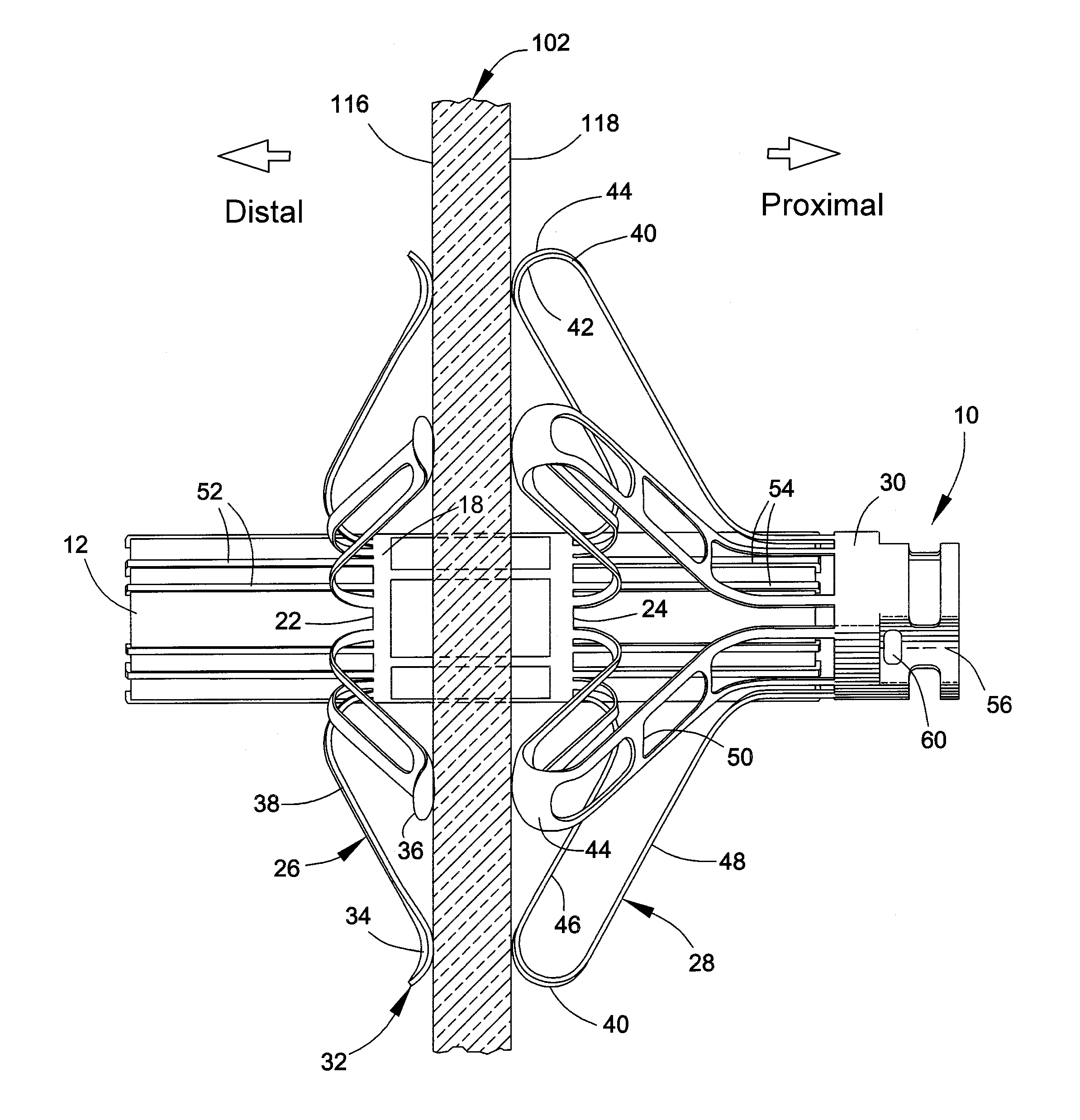
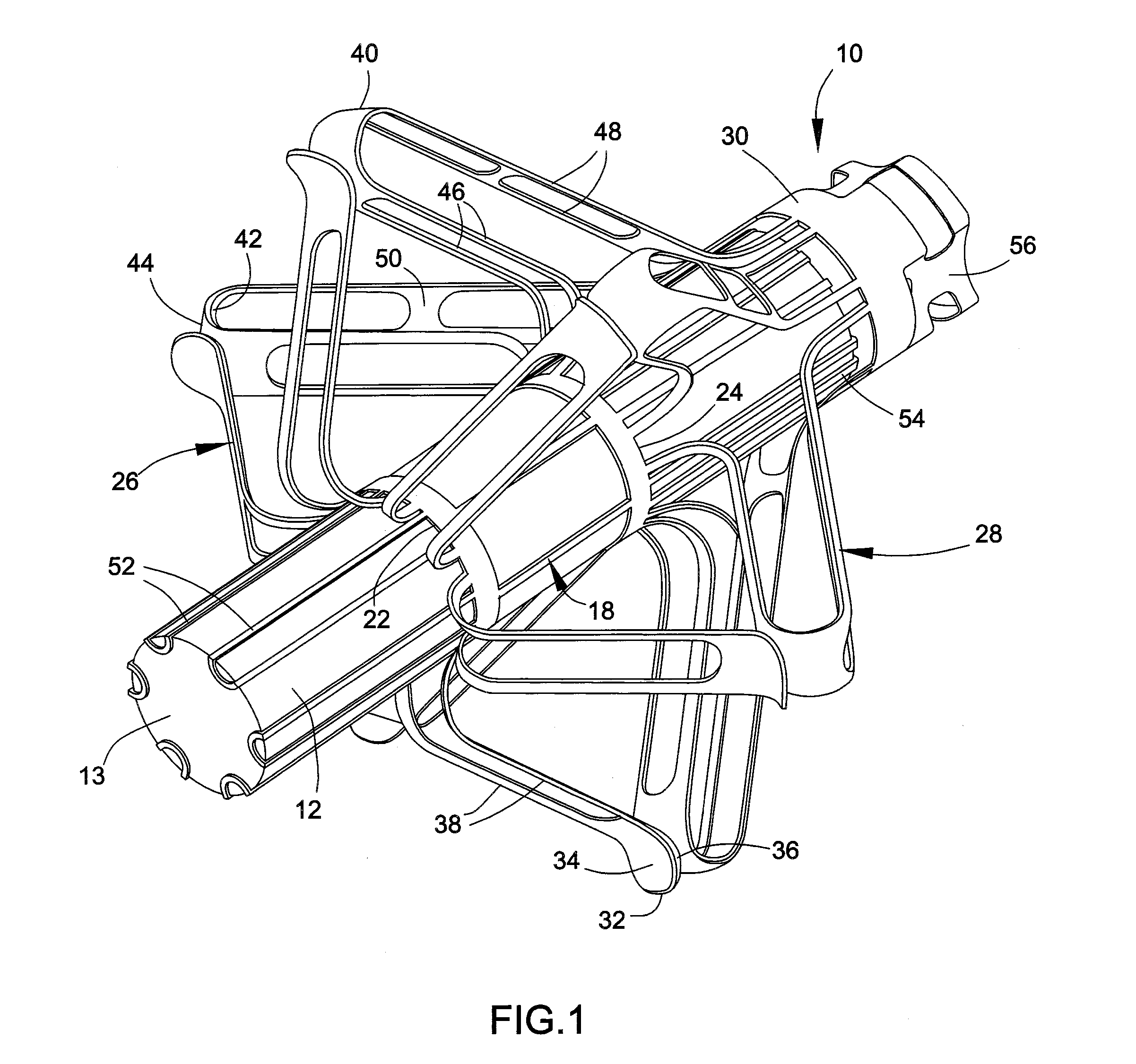
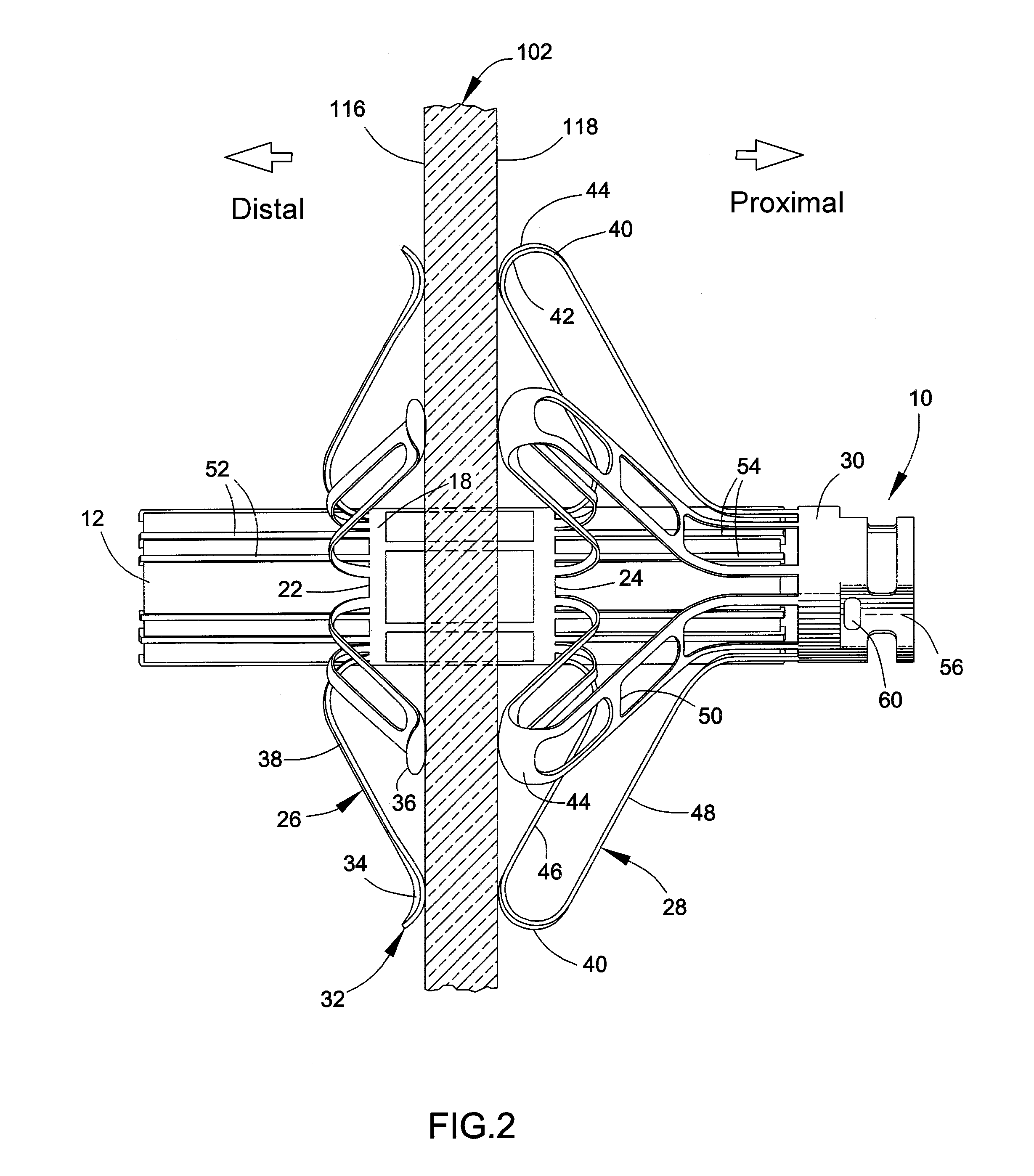
[0021]FIGS. 1 through 10 depict an anchor 10 and a delivery system 100 suitable for delivering and securing a medical implant 12 to a wall 102, such as a wall 102 of an internal organ (FIGS. 2 and 3), in accordance with an embodiment of the present invention. As a notable example, the wall 102 can be an atrial septum and the implant 12 can be employed to measure physiological parameters of the heart, such as LVEDP or MLAP. The implant 12 may be any one of a variety of types of implants currently known or developed in the future, and the scope of the present invention is not limited in any way by the type and operation of the implant 12. Implantable devices capable of being delivered with the present invention include but are not limited to wireless implants disclosed in commonly-assigned U.S. Pat. Nos. 6,926,670, 6,968,743, 7,211,048, 7,615,010 and 7,686,762 and U.S. Published Patent Application Nos. 2006 / 0047205, 2007 / 0032734, 2008 / 0077016, 2008 / 0269573, 2009 / 0005656, 2009 / 0105557,...


PUM


Abstract

A delivery system and method for placing a medical implant, such as for diagnosing, monitoring and / or treating cardiovascular diseases. The delivery system includes a hollow catheter, an anchor coupled to the catheter, and an implant secured within the anchor. The anchor has a base portion with first and second longitudinal ends and a cage therebetween. The anchor further has flexible arms, flexible legs, features for securing the medical implant within the cage of the base portion, and a coupler portion connected to and spaced apart from the second longitudinal end of the base portion. Surfaces of the arms and legs are adapted to clamp the anchor to a wall. The system further includes a pusher wire adapted to cause the anchor to acquire a stowed configuration in which the legs axially extend from the base portion, permitting the anchor to be retrieved after its deployment.

Description

CROSS REFERENCE TO RELATED APPLICATIONS[0001]This is a continuation-in-part patent application of co-pending United States patent application Ser. No. 12 / 960,961, filed Dec. 6, 2010, which claims the benefit of U.S. Provisional Application No. 61 / 283,492, filed Dec. 5, 2009. The contents of these patent documents are incorporated herein by reference.BACKGROUND OF THE INVENTION[0002]The present invention generally relates to implantable medical devices, such as of the types for monitoring physiological parameters. More particularly, the invention relates to anchors for medical implants, methods of manufacturing anchors, and methods of placing medical implants, wherein the anchors and methods are suitable for use in procedures performed to diagnose, monitor, and / or treat cardiovascular diseases, including procedures performed to monitor pressure in the left side of the heart.[0003]Congestive heart failure (CHF), a condition in which the heart fails to pump efficiently, currently affec...

Claims


Application Information

Patent Timeline
Patent Type & Authority Applications(United States)
IPC IPC(8): A61B17/00
CPCA61B5/0215A61B5/076A61B5/6869A61B5/6876A61B5/6882A61M39/0247A61F2/243A61F2/2493A61M25/02A61M25/04A61B2560/066
Inventor NAJAFI, NADERGOETZINGER, DAVID JOSEPHMORGAN, CATHERINE HOOKBARANOWSKI, JACEK RYSZARD
Owner UIM PRESSURE IMPLANT INC
Learn More