
Method, device and computer product for EEG monitoring, analysis and display

a technology for monitoring and analysis, applied in the field of patient monitoring and monitors, can solve the problems of affecting clinical decision-making, affecting the quality of life of patients,

Active Publication Date: 2014-04-29
GENERAL ELECTRIC CO
View PDF29 Cites 3 Cited by
  • Summary
  • Abstract
  • Description
  • Claims
  • Application Information

AI Technical Summary

Problems solved by technology

This possibility may vastly increase the amount of information obtained.
Due to the limited size of the display of the monitor, all the information acquired from a subject cannot be displayed to the user at one time but the user must select the information to be displayed at each time through the user interface of the monitor.
The high amount of information included in the trend-graphs may, however, delay clinical decision-making, since the user has to browse several screen pages and since the monitor cannot assist the user for speeding up the discovery of the information that may be relevant at each time and before any limits of the alarming functionality are exceeded.
This drawback is further aggravated by the fact that part of the information related to the trend-graphs may be irrelevant, because some parameters are useful only within a specific etiology group of patients.
In addition, the selection of relevant information is slowed down by the fact that some parameters are affected only in rare occasions and remain unchanged most of the time.
However, the use of fixed alarm limits or decision support systems cannot assist a clinician in detecting the less critical physiological changes and trends that may, in the course of time, lead to a life-threatening condition or to another vital change in the state of the patient.
Furthermore, clinical decision support systems are complex and expensive, due to the embedded diagnostic intelligence.

Method used


Image

  • Method, device and computer product for EEG monitoring, analysis and display
  • Method, device and computer product for EEG monitoring, analysis and display
  • Method, device and computer product for EEG monitoring, analysis and display

Examples


Embodiment Construction

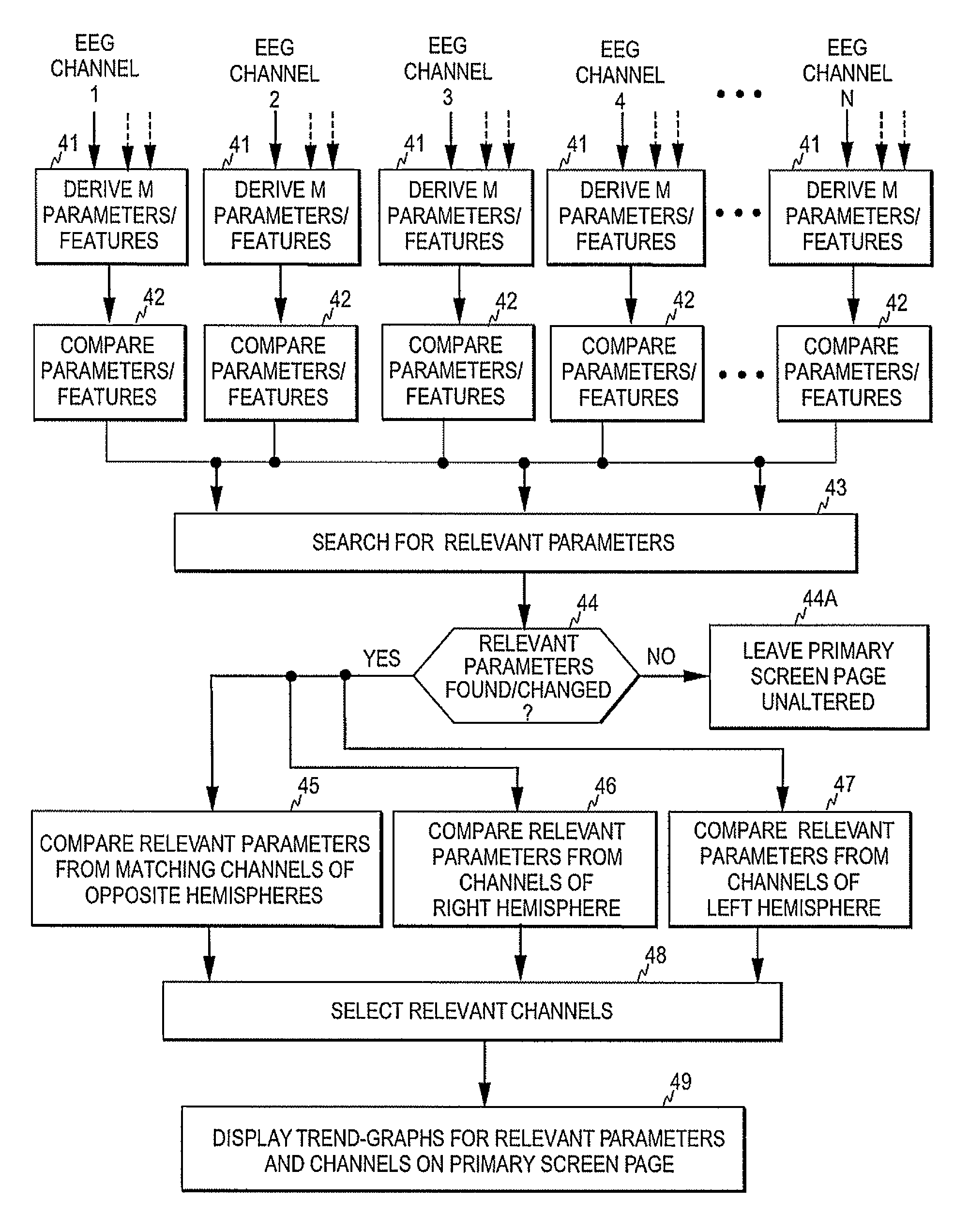
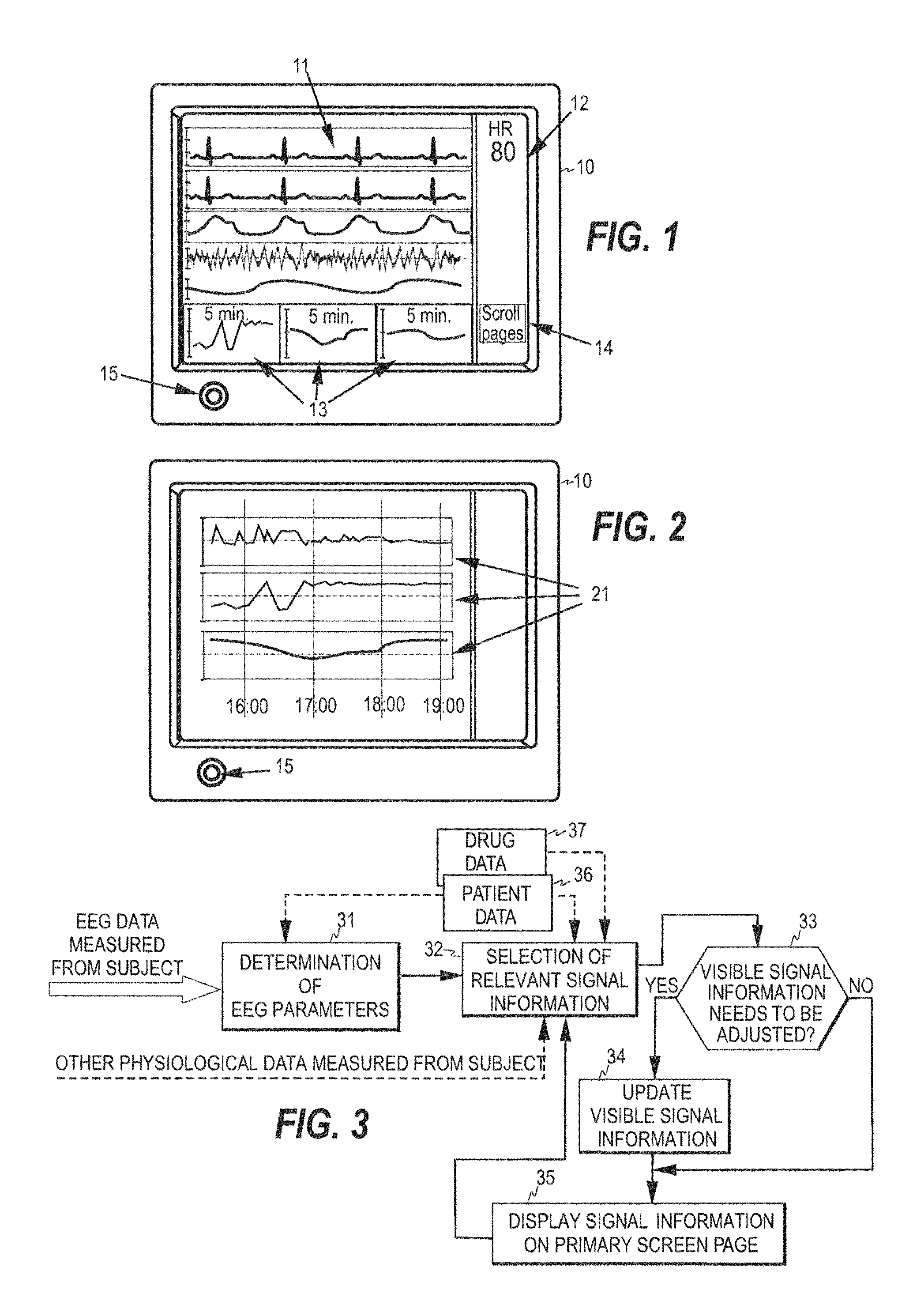
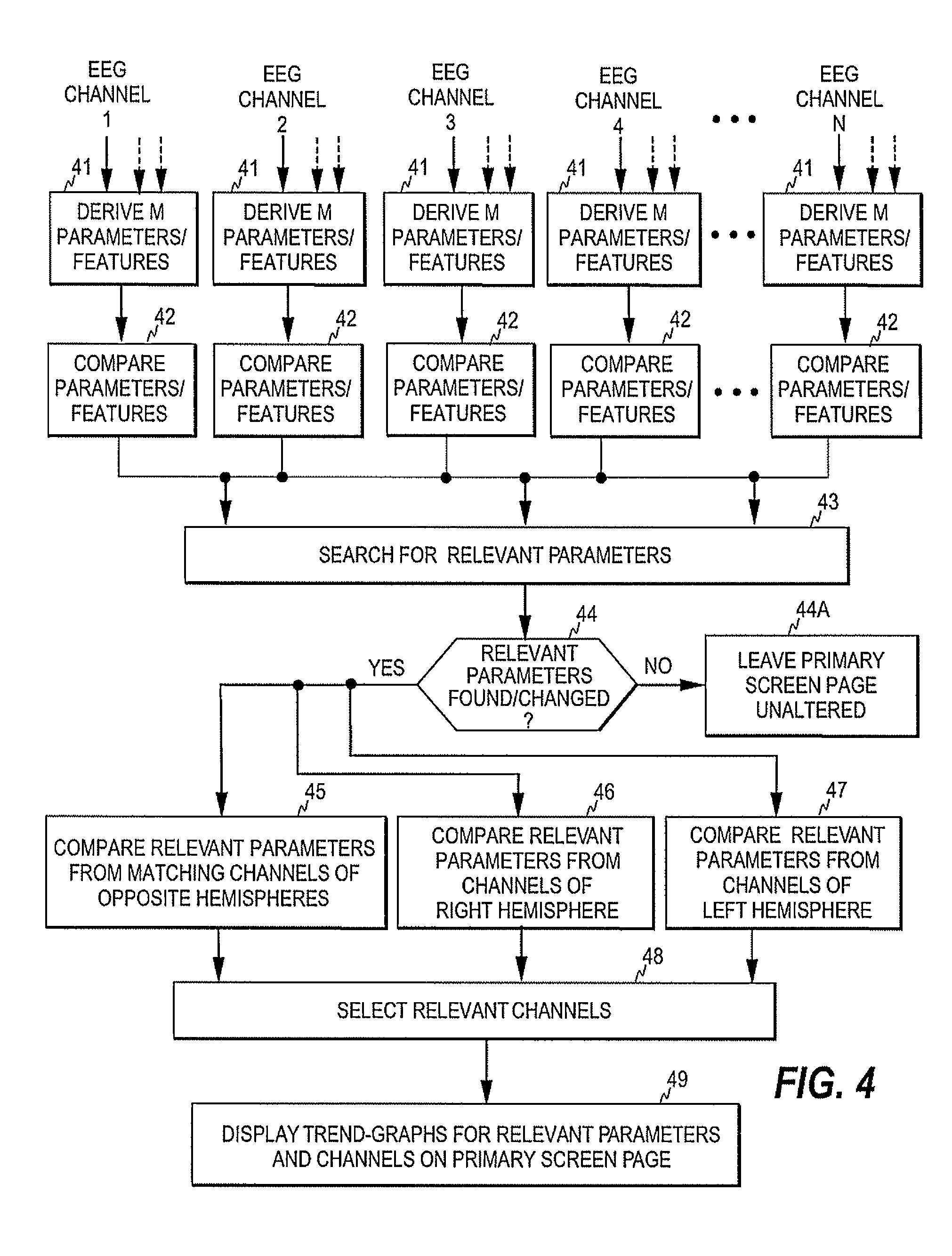
[0020]FIGS. 1 and 2 illustrate two screen pages of a multi-page patient monitor 10. As discussed above, in a multi-page monitor the information that may be displayed to the user is normally divided between a plurality of screen pages including a primary screen page displayed by default and multiple secondary screen pages that the user may select. FIG. 1 illustrates an example of the primary screen page, while FIG. 2 illustrates an example of a secondary screen page. The primary screen page typically presents waveforms 11 of a plurality of physiological signals, such as ECG, EEG, oxygen saturation, blood pressure, respiration, etc. The primary page typically also includes, for each waveform, a numerical information field 12 in which various information derived from each waveform may be presented. The primary screen may further include one or more mini-trend fields 13 each showing a short-time trend-graph of a physiological parameter measured from the subject. The monitor further incl...


PUM


Abstract

A method, device, and computer program product for monitoring the physiological state of a subject is disclosed. A first plurality of physiological signals are acquired from the subject and a second plurality of signal parameters are determined based on the first plurality of physiological signals. Relevant signal information is selected from among the signal information produced and at least one screen page is displayed at a time, thereby to make at least part of the signal information visible to a user. The signal information visible to the user on the at least one screen page may then be revised based on the selection and without user interaction, thereby to accelerate clinical decision-making and to diminish the possibility of undetected changes in the state of the subject.

Description

BACKGROUND OF THE INVENTION[0001]This disclosure relates generally to patient monitoring. More particularly, the present invention relates to patient monitoring and monitors, in which several physiological parameters are derived from a subject and various signal information, such as the time evolutions of the parameters, may be presented to the user. The physiological signal data involved may be, for example, EEG signal data.[0002]Patient monitors are electronic devices designed to display physiological information about a subject. Electrocardiogram (ECG), electroencephalogram (EEG), plethysmographic signals, and signals related to blood pressure, temperature, and respiration represent typical physiological information contained in full-size patient monitors. A patient monitor may also be designed to display physiological information from one organ only; a full-size EEG monitor, for example, may display EEG signal information from even 64 measurement channels. The EEG monitors curre...

Claims


Application Information

Patent Timeline
Patent Type & Authority Patents(United States)
IPC IPC(8): A61B5/00A61B5/0476G16H40/63
CPCG16H40/63G16H50/30G16H50/20G16H15/00Y10S128/923Y10S128/925A61B5/372A61B5/384A61B5/72A61B5/7221A61B5/7235A61B5/743A61B2505/01A61B2505/03A61B2505/05
Inventor SARKELA, MIKA
Owner GENERAL ELECTRIC CO
Learn More