
Self-adaptive mechanical finger and method

a mechanical finger and self-adaptive technology, applied in the direction of manipulators, load-engaging elements, gripping heads, etc., can solve the problems of robotic hands that have little, if any, success outside research laboratories, and the complexity of controlling often more than 12 axes, and achieve the effect of not constraining the degree of freedom of mechanical fingers

Active Publication Date: 2014-05-13
POLYVALOR LP
View PDF17 Cites 13 Cited by
  • Summary
  • Abstract
  • Description
  • Claims
  • Application Information

AI Technical Summary

Problems solved by technology

Nevertheless, only a handful of prototypes are currently known.
These devices have been developed with the aim of matching the human hands in terms of dexterity and adaptation capabilities, a difficult challenge with the currently available technologies.
However, these prototypes have all been designed aiming at an anthropomorphic architecture where each joint is independently actuated and the complexity of controlling often more than 12 axes, simultaneously and in real time, is especially demanding and yields significant costs.
Hence, despite their capabilities, robotic hands have often little, if any, success outside research laboratories.

Method used


Image

  • Self-adaptive mechanical finger and method
  • Self-adaptive mechanical finger and method
  • Self-adaptive mechanical finger and method

Examples


examples

Comparison of Two-Phalanx Architectures

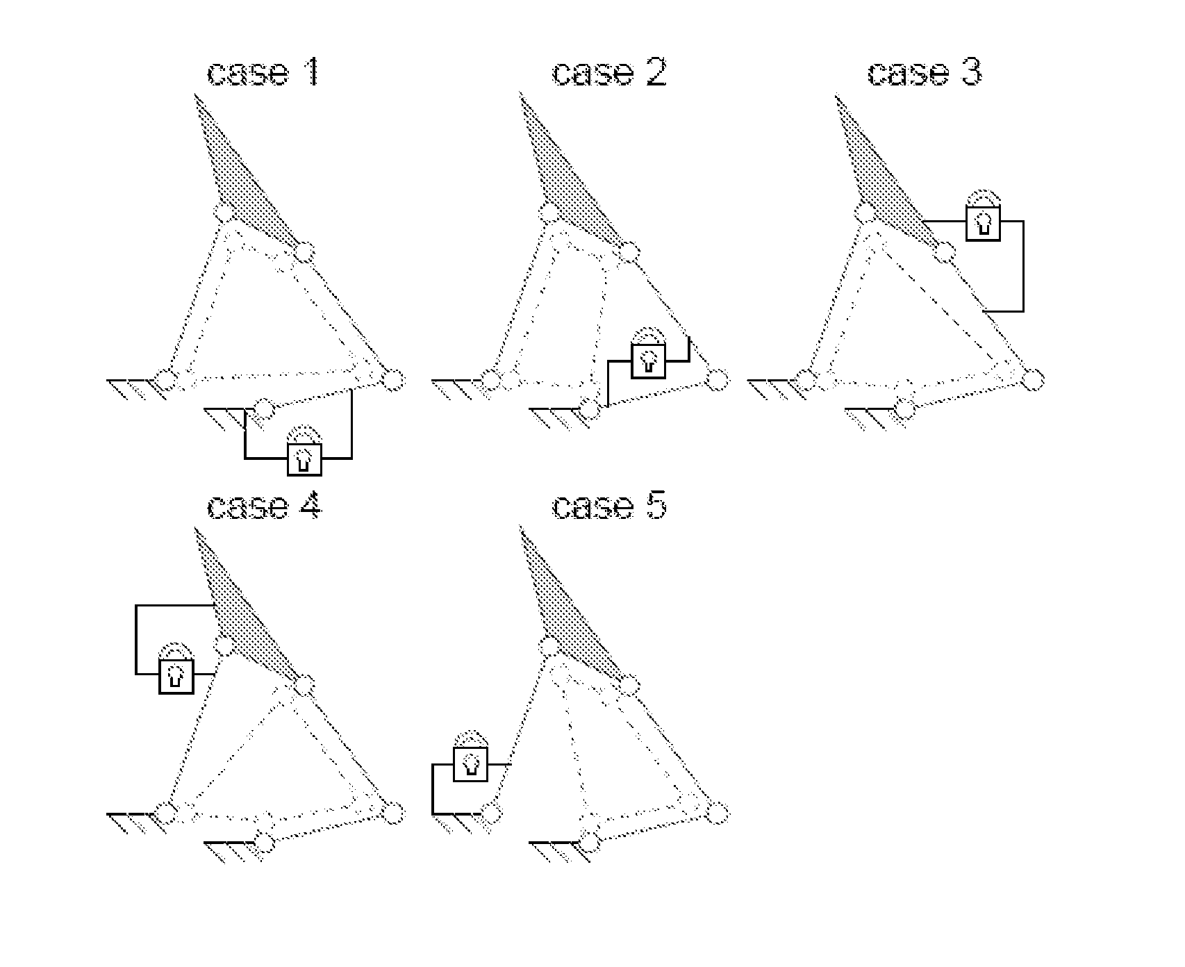
[0102]The tools presented herein can be used to compare the different architectures of two-phalanx fingers obtained above. As an example, it is supposed that one wants to select an architecture among the latter to design a self-adaptive finger. It is assumed that only revolute joints are acceptable, and that the designer desires a transmission linkage with only one attachment to the ground. Due to the latter hypothesis, the architectures A345, A734, B234, C612 and C673 are eliminated, leaving 14 valid choices. With the geometric parameters presented in FIG. 14, where the torque nomenclature in the transmission linkage is detailed, the expressions of the corresponding Selection matrices are presented in FIG. 15. Again, due to the complexity of the symbolic expressions of these matrices, only numerical results (rounded to one digit) are presented with the geometric parameters and configurations corresponding to FIG. 16.

[0103]To evaluate the remai...


PUM


Abstract

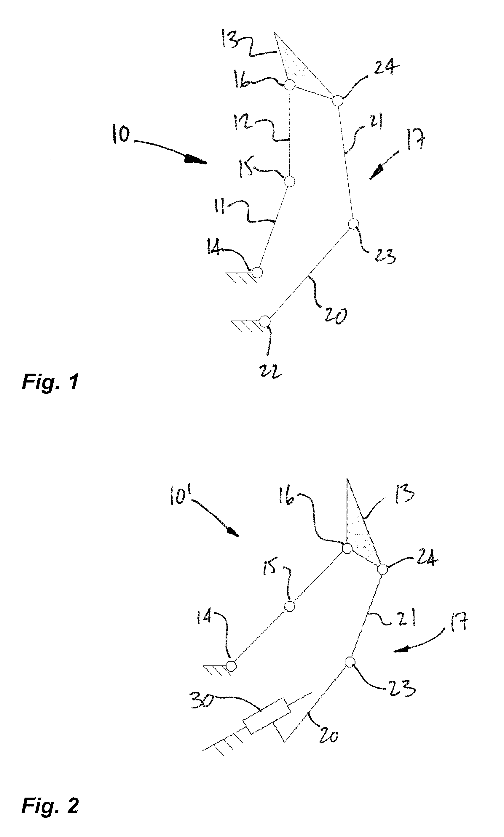
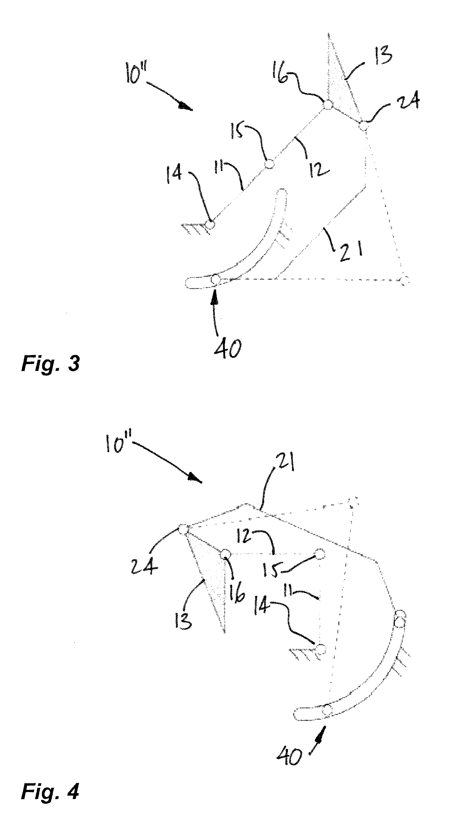
A mechanical finger comprises at least three phalanges, with a base phalanx pivotally connected at a proximal end to a base. At least one intermediate phalanx is pivotally connected at a proximal end to a distal end of the base phalanx. An end phalanx is pivotally connected at a proximal end to a distal end of a distal-most one of the at least one intermediate phalanx. The phalanges pivot about parallel pivot axes. A transmission linkage is between the base and the end phalanx. The transmission linkage has links and joints unconnected to any of the phalanges other than the end phalanx, the transmission linkage being configured so as not to constrain the degrees of freedom of the mechanical finger.

Description

CROSS-REFERENCE TO RELATED APPLICATIONS[0001]The present application claims priority on U.S. Provisional Patent Applications No. 61 / 145,817, filed on Jan. 20, 2009, and No. 61 / 165,982, filed on Apr. 2, 2009, both incorporated herein by reference.FIELD OF THE APPLICATION[0002]The present application relates to a method of synthesizing mechanical architectures of self-adaptive robotic fingers driven by linkages.BACKGROUND OF THE ART[0003]Self-adaptive mechanisms are used in robotic fingers to provide the latter with the ability to adjust themselves to the shape of the object seized without any dedicated electronics, sensor or control. Because of the lack of commercial and industrial success of complex robotic hands, self-adaptive mechanisms have attracted much more interest from the research community and several prototypes have been built. Nevertheless, only a handful of prototypes are currently known.[0004]Robotic hands are arguably the most popular end-effectors of robotic systems,...

Claims


Application Information

Patent Timeline
Patent Type & Authority Patents(United States)
IPC IPC(8): B66C1/00
CPCY10S901/39B25J15/08B25J15/0009
Inventor BIRGLEN, LIONEL
Owner POLYVALOR LP
Learn More