Check patentability & draft patents in minutes with Patsnap Eureka AI!

Machine tool

a technology for machine tools and workpieces, applied in the field of machine tools, can solve the problems of difficult supply of short workpieces to the automatic lathe, and the difficulty of smooth supply, and achieve the effects of convenient and continuous supply of short workpieces, smooth supply of various workpieces, and simple structur

Active Publication Date: 2014-05-20
CITIZEN WATCH CO LTD
View PDF12 Cites 0 Cited by
  • Summary
  • Abstract
  • Description
  • Claims
  • Application Information

AI Technical Summary

Benefits of technology

[0013]According to the first aspect of the work supplying apparatus of the invention, because the holding means provided at the end of the work pushing means holds the workpiece, and pushes and supplies the workpiece from a rear end of the spindle, it becomes possible to supply various workpieces smoothly.
[0014]Moreover, because the work supplying means has a work moving means for moving the workpiece so as to be held by the holding means, it becomes possible to automate the supply of the workpiece to the holding means and to supply a large number of short-length workpieces readily and continuously.
[0015]According to the arrangement described in the second aspect of the work supplying apparatus of the invention, because the work moving means comprises a pusher for pushing the workpiece to the holding means, it becomes possible to hold various workpieces by the holding means with a simple structure.
[0016]According to the arrangement described in the third aspect of the work supplying apparatus of the invention, because the work supplying means has a positioning means for positioning the holding means in holding the workpiece, the holding means can hold the workpiece more smoothly and more securely.
[0017]According to the arrangement described in the fourth aspect of the work supplying apparatus of the invention, because the work moving means is movable to the operating position for moving the workpiece to the holding means, and to the receding position for permitting the work pushing means to supply the workpiece to the spindle, it readily becomes possible to switch the movement of the workpiece to the holding means and the supply of the workpiece by the work pushing means.
[0018]According to the arrangement described in the fifth aspect of the work supplying apparatus of the invention, the work supplying apparatus of the invention can be applied without modifying a conventional long rod member supplying bar feeder, and various workpieces can be supplied, to an automatic lathe or other machine tool, from the work supplying apparatus of the invention or from the bar feeder.

Problems solved by technology

However, the former work supplying apparatus has a problem that it is not easy to supply short workpieces to the automatic lathe because it does not support the short workpieces.
The latter work supplying apparatus also has a problem that, because it just pushes in the workpieces, smooth supply may become difficult depending on the shape, size and other properties of the workpieces.

Method used


Image

  • Machine tool
  • Machine tool
  • Machine tool

Examples


embodiment

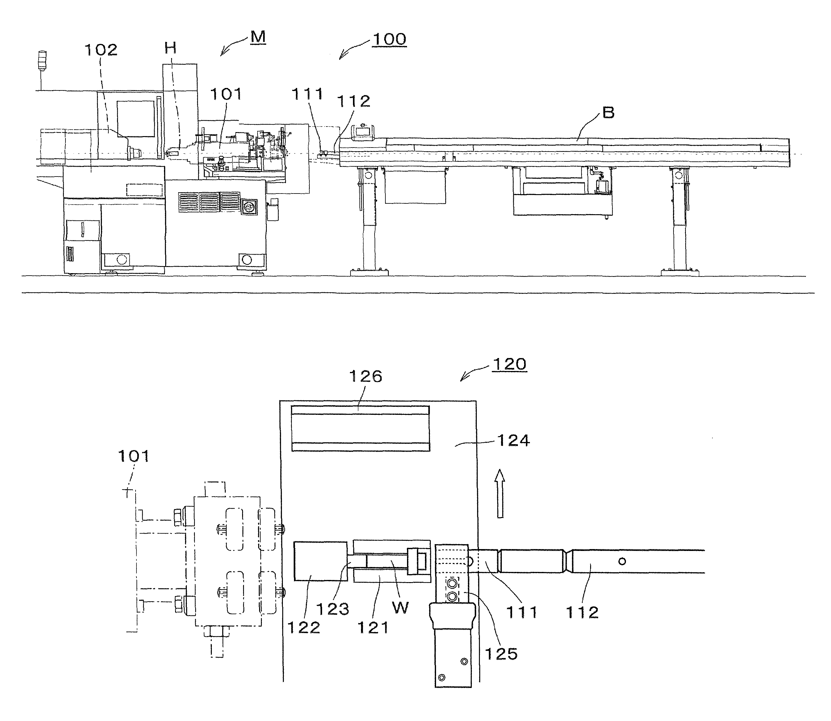
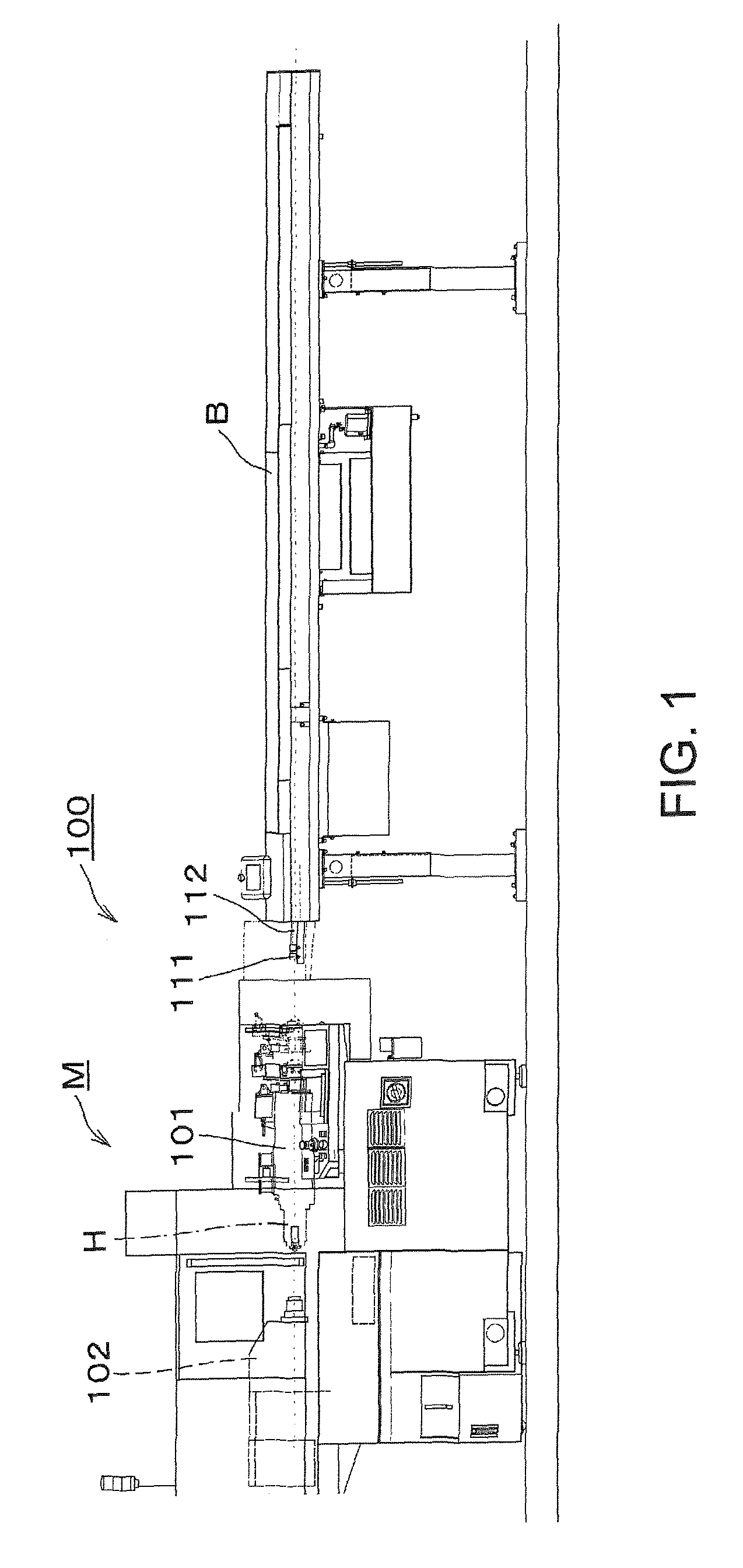
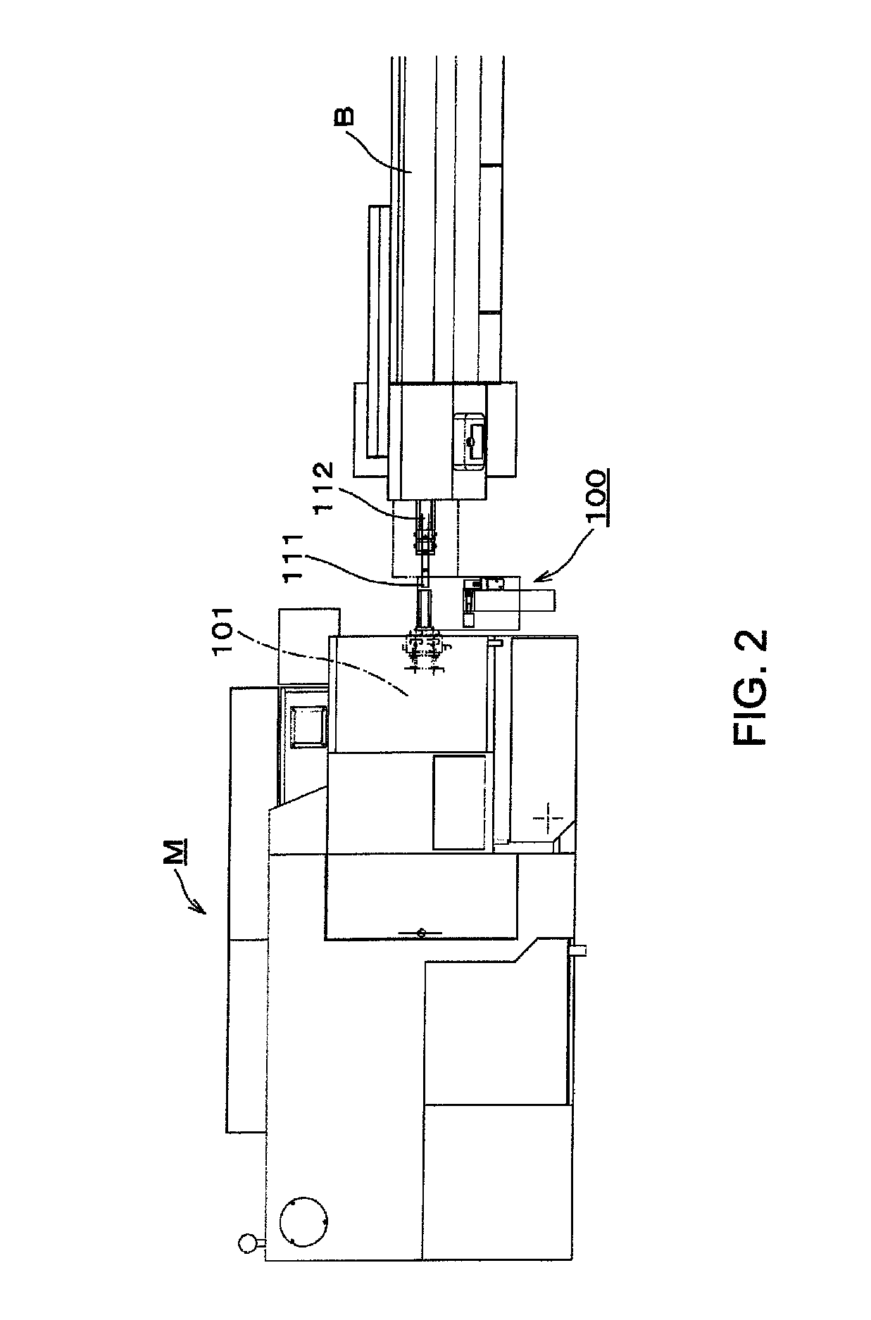
[0031]FIGS. 1 and 2 show a processing system comprising a work supplying apparatus 100 of an embodiment of the invention. In the arrangement of the processing system, the work supplying apparatus 100 is disposed between an automatic lathe M and a bar feeder B.

[0032]The automatic lathe M is a known automatic lathe and has a rotatable and drivable hollow spindle 101. A chuck H as shown in FIG. 8 is provided at a front end of the spindle 101 so that a processing tool can machine a workpiece gripped by the chuck H.

[0033]The bar feeder B is a known bar feeder having a body within which a long rod member is stored, and has a feed rod 112 slidable in the direction of the axis of spindle 101 of the automatic lathe M. The bar feeder B and the automatic lathe M are disposed so that the feed rod 112 and the spindle 101 are positioned on the same axial line.

[0034]A finger chuck 111 for holding the rear end of a rod member is attached at the front end of the feed rod 112 to serve as a holding me...


PUM

PropertyMeasurementUnit
shapeaaaaaaaaaa
sizeaaaaaaaaaa
lengthaaaaaaaaaa

Abstract

There is provided a work supplying apparatus for automatically and smoothly supplying workpieces having various shapes and sizes from a rear end of a hollow spindle in a machine tool or assembling machine. The work supplying apparatus has a work pushing means for pushing the workpiece held by a holding means into a chuck, and a pusher for pushing and holding the workpiece supplied to a work receiver in the direction of the holding means.

Description

TECHNICAL FIELD[0001]The present invention relates to a work supplying apparatus for supplying workpieces to an operating machine such as a machine tool and to a processing system having such work supplying apparatus.BACKGROUND ART[0002]Hitherto, it has been a widely used technology to supply workpieces into a hollow spindle having a chuck at a front end by pushing them from a rear end thereof. A work supplying apparatus therefor is also known.[0003]For instance, there has been known a work supplying apparatus for supplying long workpieces by pushing them into a hollow spindle from a rear end by means of a bar feeder having a feed rod with a finger chuck for holding the workpieces at a front end thereof in order to feed the workpieces sequentially to machine tools such as an automatic lathe, as disclosed in Japanese Laid-open Utility Model Application No. S59-156705 (Page 1, FIG. 1) for example.[0004]There has been also known a work supplying apparatus for supplying short workpieces...

Claims


Application Information

Patent Timeline
Patent Type & Authority Patents(United States)
IPC IPC(8): B23B15/00B23B13/02
CPCB23B13/02B23B13/123B23B7/00B23Q7/001Y10T82/2514Y10T82/2521Y10T82/2516
Inventor NAKAYA, TAKAICHIYANAGIDAIRA, SHIGEOYABE, KOICHI
Owner CITIZEN WATCH CO LTD
Features
  • R&D
  • Intellectual Property
  • Life Sciences
  • Materials
  • Tech Scout
  • Unparalleled Data Quality
  • Higher Quality Content
  • 60% Fewer Hallucinations
Learn More