Hydraulic braking pressure generating apparatus for vehicles

a technology of hydraulic braking and generating apparatus, which is applied in the direction of braking systems, rotary clutches, fluid couplings, etc., can solve the problems of limiting and inability to prevent strokes of stroke simulators, and achieve the effect of large braking for

Inactive Publication Date: 2005-05-26
ADVICS CO LTD
View PDF6 Cites 20 Cited by
  • Summary
  • Abstract
  • Description
  • Claims
  • Application Information

AI Technical Summary

Benefits of technology

[0010] Accordingly, it is an object of the present invention to provide a hydraulic braking pressure generating apparatus for vehicles, which is provided with a braking stroke simulator, and which is capable of obtaining a proper brake feeling...

Problems solved by technology

According to the apparatuses as described above, however, when the air-bleeding operation is performed after it was installed on a vehicle, even if the changeover device was actuated, the stroke of the stroke simulator could not be prevented from being stroked, due to insufficiency of brake fluid to be filled, whereby bo...

Method used


Image

  • Hydraulic braking pressure generating apparatus for vehicles
  • Hydraulic braking pressure generating apparatus for vehicles
  • Hydraulic braking pressure generating apparatus for vehicles

Examples


Embodiment Construction

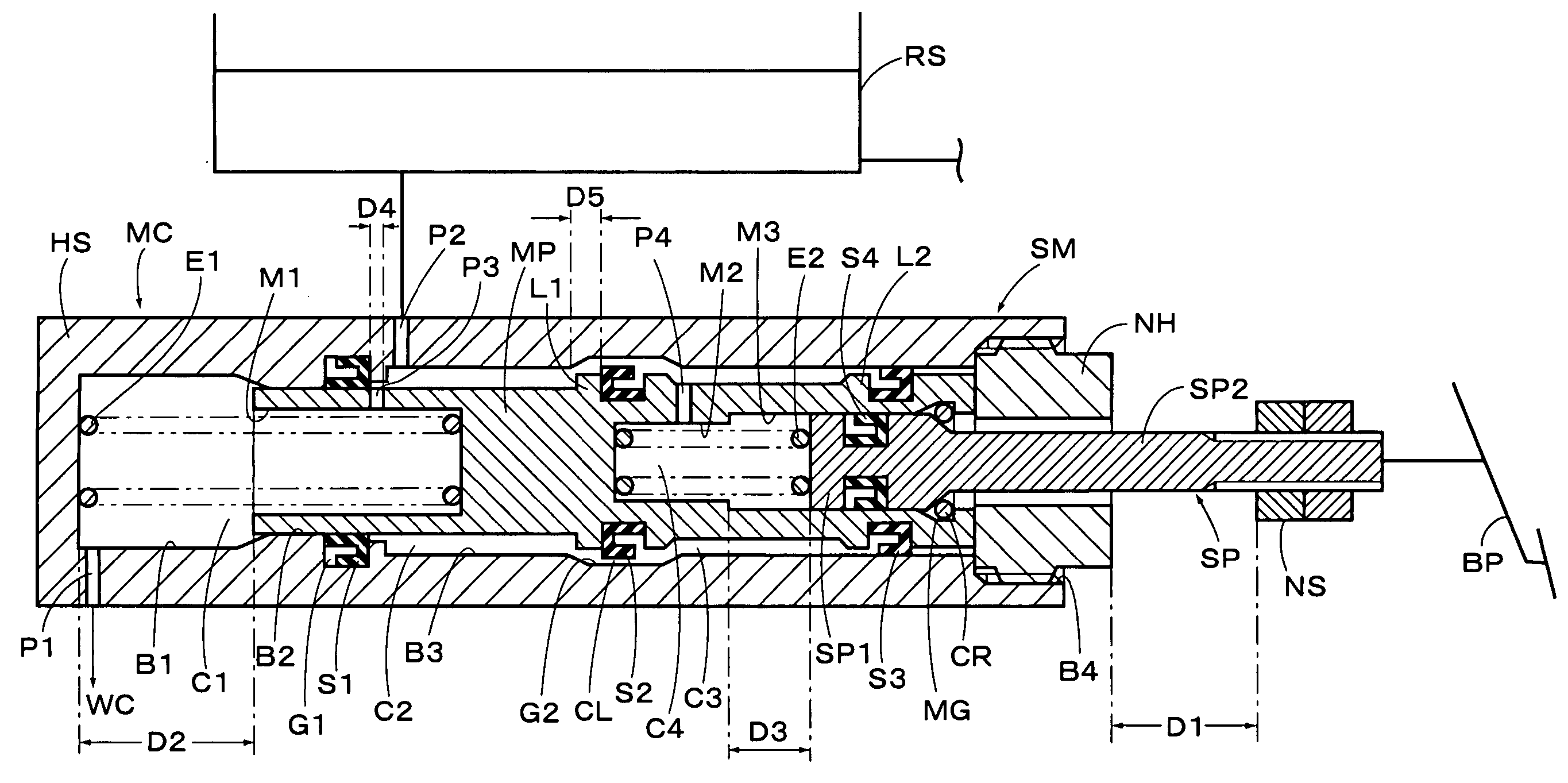
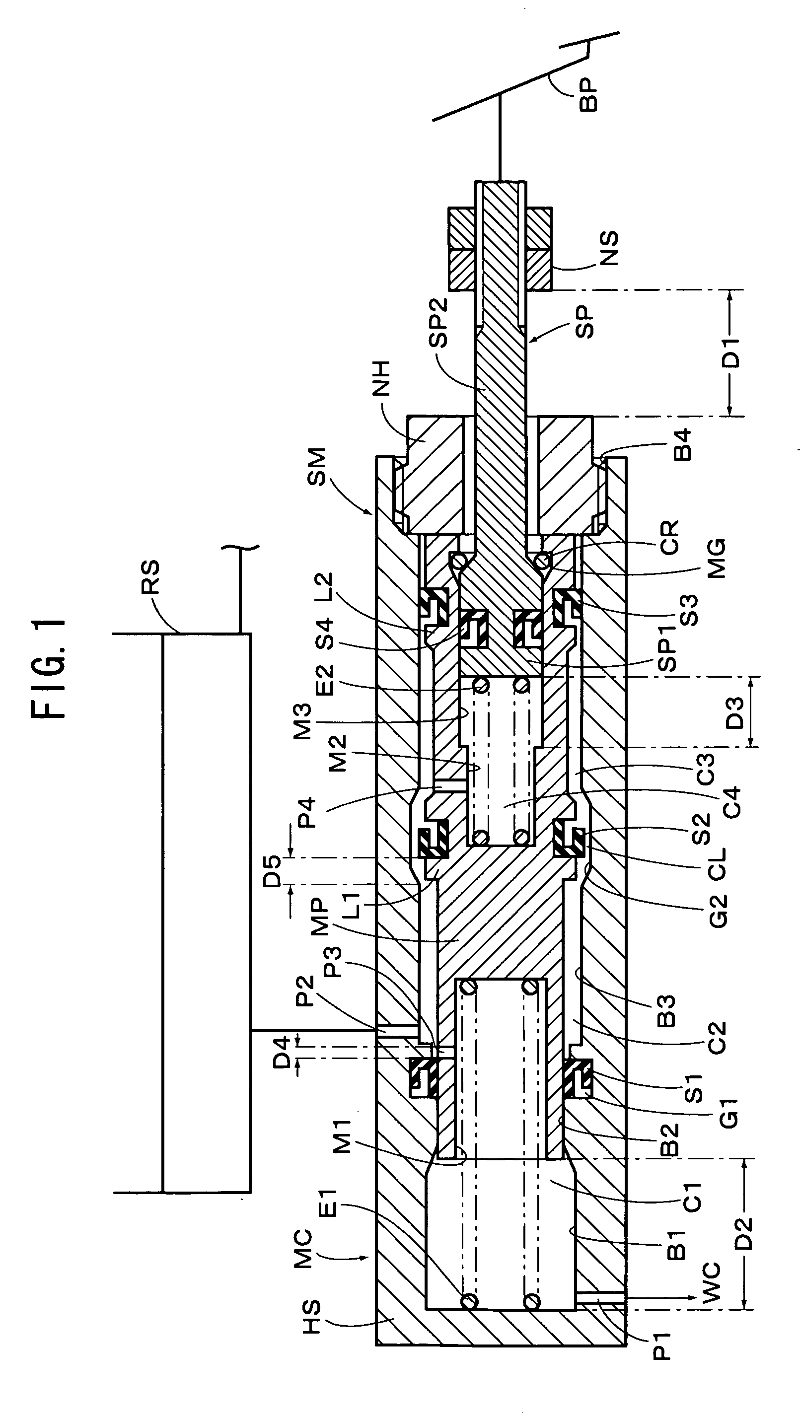
[0030] Referring to FIG. 1, there is illustrated a hydraulic braking pressure generating apparatus for vehicles according to an embodiment of the present invention, wherein a master cylinder MC and a stroke simulator SM are formed in a body, and wherein a master piston MP served as the second piston member of the present invention is slidably accommodated in a cylinder housing HS (hereinafter, simply referred to as housing HS). Furthermore, a simulator piston SP served as the first piston member of the present invention is slidably accommodated in the master piston MP. The housing HS is closed in its front end (left in FIG. 1) to be formed in a cylinder with a bottom, and formed with a cylinder bore having a stepped bore of a recess B1, a small diameter bore B2 and a large diameter bore B3. At the rear end of the housing HS, there is formed an open end portion B4 with threaded grooves formed on its inner surface. On the inner surface of the small diameter bore B2, an annular groove ...


PUM


Abstract

A pressure generating apparatus includes a first piston moved in response to operation of a brake pedal, an elastic member for providing a stroke of the first piston in response to braking operation force of the brake pedal, a second piston accommodated in a housing for defining a master chamber in front of it and a simulator chamber at the back of it, and an atmospheric pressure reservoir for storing brake fluid. A changeover device is provided for selectively communicating the simulator chamber with the reservoir, or blocking the communication between them. And, a stroke restriction device is provided for restricting a maximal stroke of the first piston relative to the housing to be smaller than the sum of a maximal stroke of the second piston relative to the housing and a maximal stroke of the first piston relative to the second piston.

Description

[0001] This application claims priorities under 35 U.S.C. Sec. 119 to Nos. 2003-391650 and 2003-391651 filed in Japan on Nov. 21, 2003, the entire contents of which are herein incorporated by reference. BACKGROUND OF THE INVENTION [0002] 1. Field of the Invention [0003] The present invention relates to a hydraulic braking pressure generating apparatus for vehicles, and more particularly, the hydraulic braking pressure generating apparatus provided with a barking stroke simulator. [0004] 2. Description of the Related Arts [0005] Heretofore, there are known various hydraulic braking pressure generating apparatuses for vehicles, which are provided with braking stroke simulators. Among them, such an apparatus as discussed below has been disclosed in Japanese Patent Laid-open publication No. 11-59349. According to this publication, may be derived such an apparatus as constituted by a first piston which is moved back and forth in response to operation of a brake pedal, an elastic member w...

Claims


Application Information

Patent Timeline
IPC IPC(8): B60T8/40B60T11/16
CPCB60T8/4081B60T11/16B60T8/409
Inventor KUSANO, AKIHITO
Owner ADVICS CO LTD
Why Eureka
Try Eureka