Electric power assisting device of braking system and running method of electric power assisting device

A technology of electric power assist and braking system, which is applied in the direction of braking transmission, brake, transportation and packaging, etc. It can solve the problem of relatively high consistency of fluid demand, shorten the braking distance, increase the braking force, The effect of improving safety performance

Active Publication Date: 2012-05-09
CHERY AUTOMOBILE CO LTD
View PDF6 Cites 15 Cited by
  • Summary
  • Abstract
  • Description
  • Claims
  • Application Information

AI Technical Summary

Problems solved by technology

But its disadvantage is that the absolute displacement of the input part is only used as the basis for calculation, and the consistency requirements for other components of the brake system are relatively high.

Method used


Image

  • Electric power assisting device of braking system and running method of electric power assisting device
  • Electric power assisting device of braking system and running method of electric power assisting device
  • Electric power assisting device of braking system and running method of electric power assisting device

Examples


Embodiment Construction

[0028] The present invention will be described in detail below according to the accompanying drawings, which is a preferred embodiment among various implementations of the present invention.

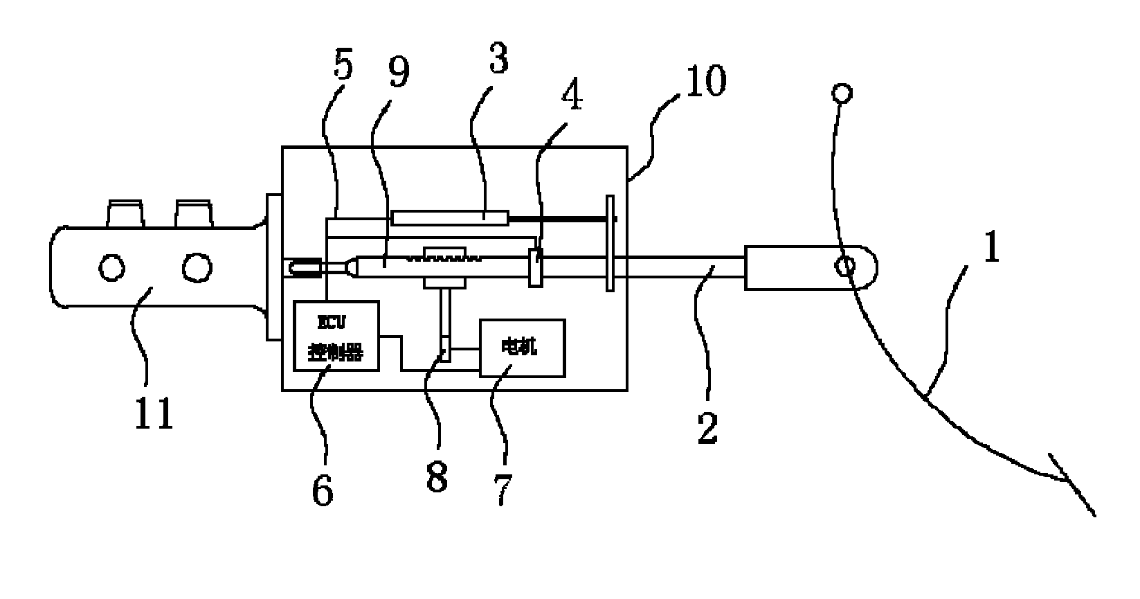
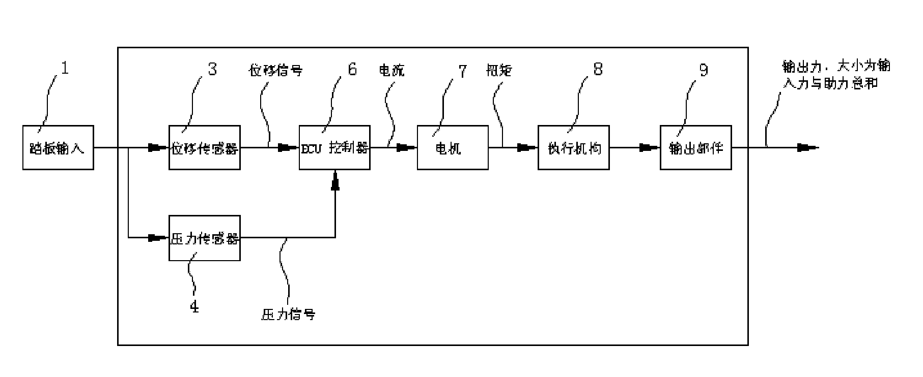
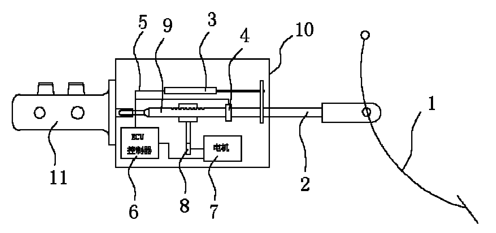
[0029] Such as figure 1 As shown, the booster device of the present invention is composed of an input part 2, a displacement sensor 3, a pressure sensor 4, a connecting wire harness 5, a controller assembly 6, a direct drive motor 7, an actuator 8, an output part 9 and a housing assembly 10. . The input part 2 is connected with the brake pedal 1, and the input part 2 can rotate plus or minus 5 degrees relative to the axial direction of the booster device. One end of the displacement sensor 3 is fixed, and the other end is connected to the input part 2, and moves axially with the input part 2 synchronously. When the driver steps on the brake pedal 1, the displacement sensor 3 will collect the relative displacement of the input part 2, and then connect the wiring harness 5 transmits the ...


PUM


Abstract

The invention relates to an electric power assisting device of a braking system and a running method of the electric power assisting device. The electric power assisting device comprises a pressure sensor, a controller assembly, an actuating mechanism and a direct drive motor, wherein the pressure sensor is connected with a brake pedal and used for acquiring pressure signals from the brake pedal, the controller assembly is connected to the pressure sensor by a connecting wire harness or connected to the pressure sensor wirelessly and is used for receiving the pressure signals and carrying out logic operation, furthermore, the controller assembly is connected to the direct drive motor by a connecting wire harness or connected with the direct drive motor wirelessly and is used for transmitting control signals obtained via logic operation to the direct drive motor, and the direct drive motor is in drive connection with the actuating mechanism and drives the actuating mechanism to realize electric power boosting.

Description

technical field [0001] The invention relates to the field of automobile braking systems, in particular to an electric power booster for a braking system and an operating method thereof. Background technique [0002] Electric vehicles are the trend of automobile development. Compared with traditional gasoline engine vehicles, electric vehicles cannot provide the vacuum source required by the vacuum booster of the braking system, so it is necessary to develop a new booster to replace the original vacuum booster. At present, in the known technology, the technical materials similar to the technical effect of the present invention are: [0003] 1. CN200710111537.5 An electric power-assisted braking system. Its main structure is composed of a motor, a reduction mechanism, a transmission mechanism and a controller. The output shaft of the motor is connected to the input end of the reduction mechanism, and the output end of the reduction mechanism is connected to the transmission me...

Claims


Application Information

Patent Timeline
Patent Type & Authority Applications(China)
IPC IPC(8): B60T13/74B60T8/17
Inventor 张德志李彬赖锋
Owner CHERY AUTOMOBILE CO LTD
Why Eureka
Try Eureka