Control device for electric vehicle

A technology for electric vehicles and control devices, applied in control devices, battery/fuel cell control devices, electric vehicles, etc., can solve problems such as inability to ensure vehicle stability and braking force differences

Active Publication Date: 2016-04-13
HITACHI ASTEMO LTD
View PDF14 Cites 11 Cited by
  • Summary
  • Abstract
  • Description
  • Claims
  • Application Information

AI Technical Summary

Problems solved by technology

Therefore, when there is a difference in the slip ratio of the left and right wheels, there is a difference in the braking force between the l

Method used


Image

  • Control device for electric vehicle
  • Control device for electric vehicle
  • Control device for electric vehicle

Examples


Embodiment 1

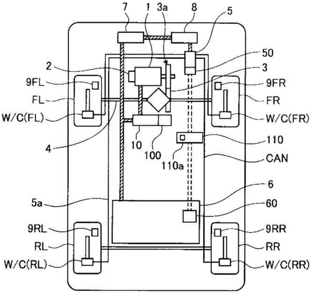
[0018] figure 1 It is a system diagram showing the configuration of the electric vehicle of the first embodiment. The electric vehicle is a front-wheel drive vehicle and has front wheels FR, FL as drive wheels and rear wheels RR, RL as driven wheels. Each wheel is equipped with sub-cylinders W / C(FR), W / C(FL), W / C(RR) that press the brake pads against the brake rotor that rotates integrally with the tire to generate frictional braking force, W / C (RL) (also referred to as W / C for short), and wheel speed sensors 9 (FR), 9 (FL), 9 (RR), 9 (RL) (also referred to as 9.). A hydraulic unit 5 is connected to the slave pump W / C via a hydraulic piping 5 a.

[0019] The hydraulic unit 5 is equipped with a plurality of solenoid valves, a liquid storage tank, a pump motor, and a brake controller 50. According to instructions from the brake controller 50, the driving states of various solenoid valves and pump motors are controlled, and the wheels are controlled. sub-pump hydraulic pressu...


PUM


Abstract

Provided is a control device for electric vehicles, capable of stabilizing vehicle behavior when performing slip control of drive wheels. This control device for electric vehicles comprises: a motor connected to drive wheels of a vehicle, via a differential gear and a drive shaft, and generating braking/driving torque for the drive wheels; and a mechanical braking device capable of generating braking force independently from the drive wheels. The control device for vehicles is configured such that when a drive wheel slip rate of at least a prescribed value is detected: the torque absolute value of the motor is reduced such that the drive wheel slip rate reaches a target motor slip rate; and a larger braking force is applied by the mechanical braking device to the drive wheel out of the right and left drive wheels that has the higher wheel speed than is applied to the drive wheel having the lower wheel speed.

Description

technical field [0001] The present invention relates to a control device for an electric vehicle. Background technique [0002] Conventionally, the technology described in Patent Document 1 is known as a control device for an electric vehicle. In this publication, in a vehicle having an electric brake member and a second brake member, in an anti-lock brake control device that prevents locking by using any one of the above-mentioned brake members in accordance with the locked state of the wheels, when When the anti-lock control is started, the braking force corresponding to the pedaling force is gradually decreased so that the braking force of the other party not performing the anti-lock control becomes zero. [0003] prior art literature [0004] patent documents [0005] Patent Document 1: (Japanese) Patent No. 3438242 Contents of the invention [0006] The technical problem to be solved by the invention [0007] However, when applied to an electric vehicle in which ...

Claims


Application Information

Patent Timeline
IPC IPC(8): B60T8/1763B60L7/24B60T8/17B60T8/172B60T8/175
CPCB60L3/106B60L3/108B60L7/12B60L7/26B60L15/20B60L15/2009B60L2210/10B60L2240/12B60L2240/421B60L2240/423B60L2240/461B60L2240/465B60L2260/44B60T8/175B60T2201/14Y02T10/64Y02T10/70Y02T10/72B60L7/18B60L50/52B60L50/66B60L58/20
Inventor 铃木圭介
Owner HITACHI ASTEMO LTD
Why Eureka
Try Eureka