Electric disk brake

a technology of disc brake and electric disc, applied in the field of electric disc brake, can solve the problem of no back-up function, and achieve the effects of reducing the rotational speed of the motor, greater force, and greater braking for

Active Publication Date: 2010-05-27
HL MANDO CORP
View PDF7 Cites 13 Cited by
  • Summary
  • Abstract
  • Description
  • Claims
  • Application Information

AI Technical Summary

Benefits of technology

[0015]According to the electric disc brake of the present invention, the rotational speed of the motor is reduced by the worm gear and the worm wheel, so the pressing member can press the first friction pad with greater force, thereby generating greater braking force.
[0016]In addition, according to the present invention, since speed reduction may occur while rotational force of the motor is being transferred to the screw shaft, sufficient braking force can be achieved even if the motor has a small size and a low output, so that a volume of a device can be reduced.
[0017]Further, since the electric disc brake can perform the electric braking function as well as the parking assist braking function without an additional electric parking brake, the back-up function can be ensured when the electric disc brake or the electric parking brake malfunctions.
[0018]In addition, the control logic can be flexibly performed even if the load condition is changed according to the weight of the vehicle, occupants and freights.

Problems solved by technology

However, there is no back-up function when the electric disc brake or the electric parking brake malfunctions.

Method used


Image

  • Electric disk brake
  • Electric disk brake
  • Electric disk brake

Examples


Embodiment Construction

[0024]Reference will now be made in detail to the embodiments of the present invention, examples of which are illustrated in the accompanying drawings, wherein like reference numerals refer to the like elements. The embodiments are described below to explain the present invention by referring to the figures.

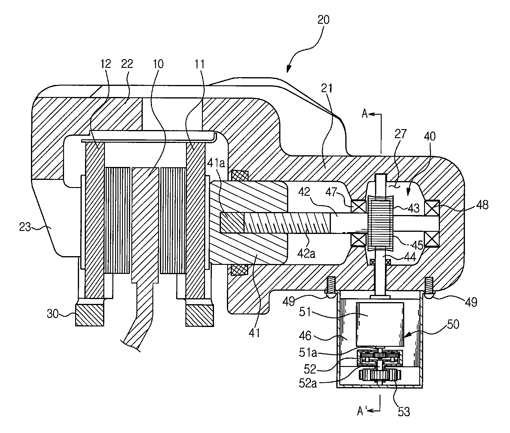
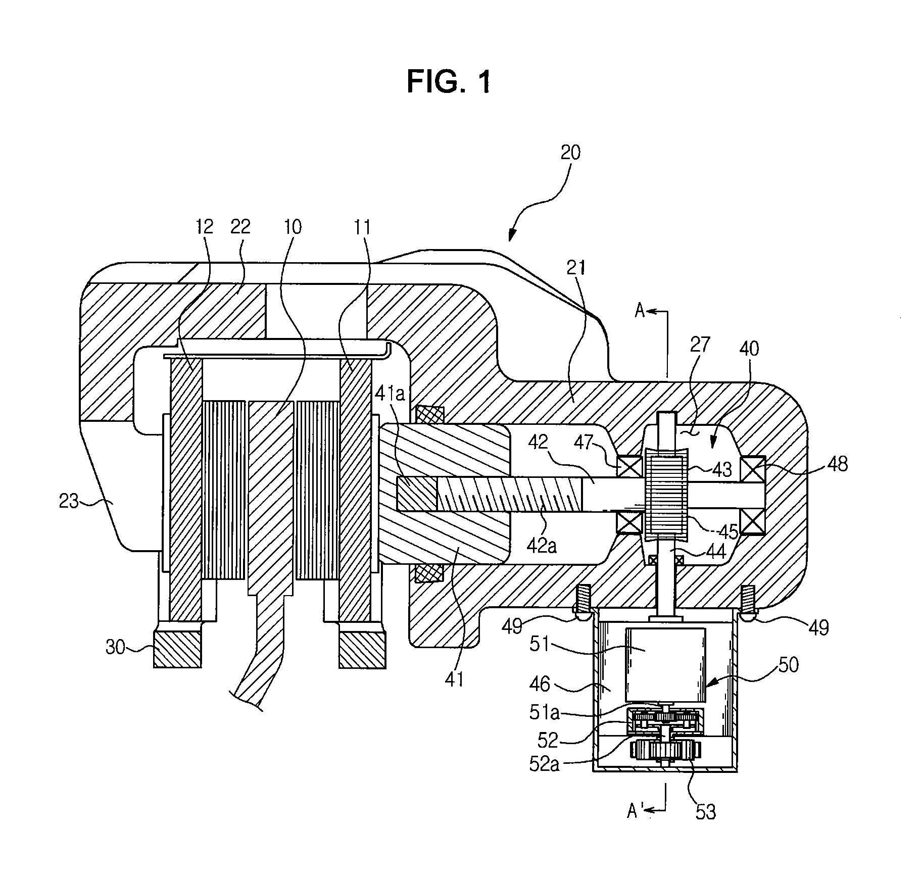
[0025]As shown in FIG. 1, an electric disc brake according to the present invention includes a disc 10 rotating together with wheels of a vehicle, first and second friction pads 11 and 12 installed at both sides of the disc 10 to perform the braking function by pressing both lateral sides of the disc 10, a caliper housing 20 for pressing the first and second friction pads 11 and 12, and a pressing device 40 installed in the caliper hosing 20 for the purpose of braking operation.

[0026]The first and second friction pads 11 and 12 are supported by a carrier 30 fixed to a vehicle body in such a manner that the first and second friction pads 11 and 12 can move back and forth with resp...


PUM


Abstract

Disclosed is an electric disc brake. The electric disc brake includes friction pads for pressing a disc, a carrier for supporting the friction pads, a caliper housing supported by the carrier such that the caliper housing moves back and forth to press the friction pads, and a pressing device for pressing the friction pads. The pressing device includes a pressing member moving back and forth in the caliper housing to press one of the friction pads, a screw shaft coupled to the pressing member, a worm wheel coupled to the screw shaft, a driving shaft crossing the screw shaft and having a worm gear engaged with the worm wheel, a motor for rotating the driving shaft in a forward direction or a reverse direction, and an auxiliary pressing device.

Description

[0001]This application claims the benefit of Korean Patent Application No. 10-2008-0117809 filed on Nov. 26, 2008, in the Korean Intellectual Property Office, the disclosure of which is incorporated herein by reference.BACKGROUND OF THE INVENTION[0002]1. Field of the Invention[0003]The present invention relates to an electric disc brake.[0004]2. Description of the Related Art[0005]Different from a typical hydraulic disc brake, an electric disc brake employs an electric motor as a power source for a driving device that presses a friction pad.[0006]Korean unexamined patent publication No. 2003-0093691 discloses such an electric disc brake. The electric disc brake includes a motor rotating in the forward or reverse direction for the purpose of braking and releasing operations, a screw gear part coupled to a rotating shaft of the motor, and a piston that presses a friction pad while moving back and forth according to rotation of the screw gear part.[0007]Meanwhile, an electric parking b...

Claims


Application Information

Patent Timeline
Patent Type & Authority Applications(United States)
IPC IPC(8): B60L7/00F16D65/18
CPCF16D65/18F16D2125/52F16D2125/40F16D2121/24F16D65/14
Inventor KIM, JOO GON
Owner HL MANDO CORP
Why Eureka
Try Eureka