Printer and printing method

a printing method and printing target technology, applied in printing, other printing apparatus, etc., can solve the problems of inability to deliver transport objects thereby, stop the printing target, and the above-mentioned drawbacks, so as to ensure improve the accuracy of the stop position, and reduce the rotational speed of the motor

Inactive Publication Date: 2008-02-28
SEIKO EPSON CORP
View PDF6 Cites 12 Cited by
  • Summary
  • Abstract
  • Description
  • Claims
  • Application Information

AI Technical Summary

Benefits of technology

[0026]With this configuration, when the motor is being driven in the controlling step, a corrected output power is calculated by comparing actual stop characteristics with reference stop characteristics in the calculating step. Then, in the outputting step, the corrected output power is output so that the stop condition of stopping the transport object is satisfied. Therefore, for example, even when the printer is used for a long time and the stop characteristics vary, it is possible to stop the motor so as to follow the predetermined stop characteristics. In this manner, even when the printer is used for a long time, it is possible to stop the transport object at a position that is not significantly deviated from the target position and possible to ensure the accuracy of the stop position. In addition, it is not necessary to, for example, decrease the rotational speed of the motor in order to improve the accuracy of the stop position, so that it is possible to improve throughput.

Problems solved by technology

Therefore, although the print target stops around the target position initially just after the printer is purchased, as the printer is used for a long time, there will be a problem in that the print target will stop at a position that is significantly deviated from the target position.
In addition, even when the way in which the supply of electric current is interrupted after the transport speed of the print target is decreased is combined with the technology described in the above publication, the above described drawback is still not removed.
Moreover, when the transport speed of the print target is an assumed speed or above as well, there is a problem in that the print target stops at a position that is deviated from the target position.
In addition, it is possible to prevent such a drawback that the transport object stops immediately before the target stop position and the transport object thereby cannot be delivered.

Method used


Image

  • Printer and printing method
  • Printer and printing method
  • Printer and printing method

Examples


Embodiment Construction

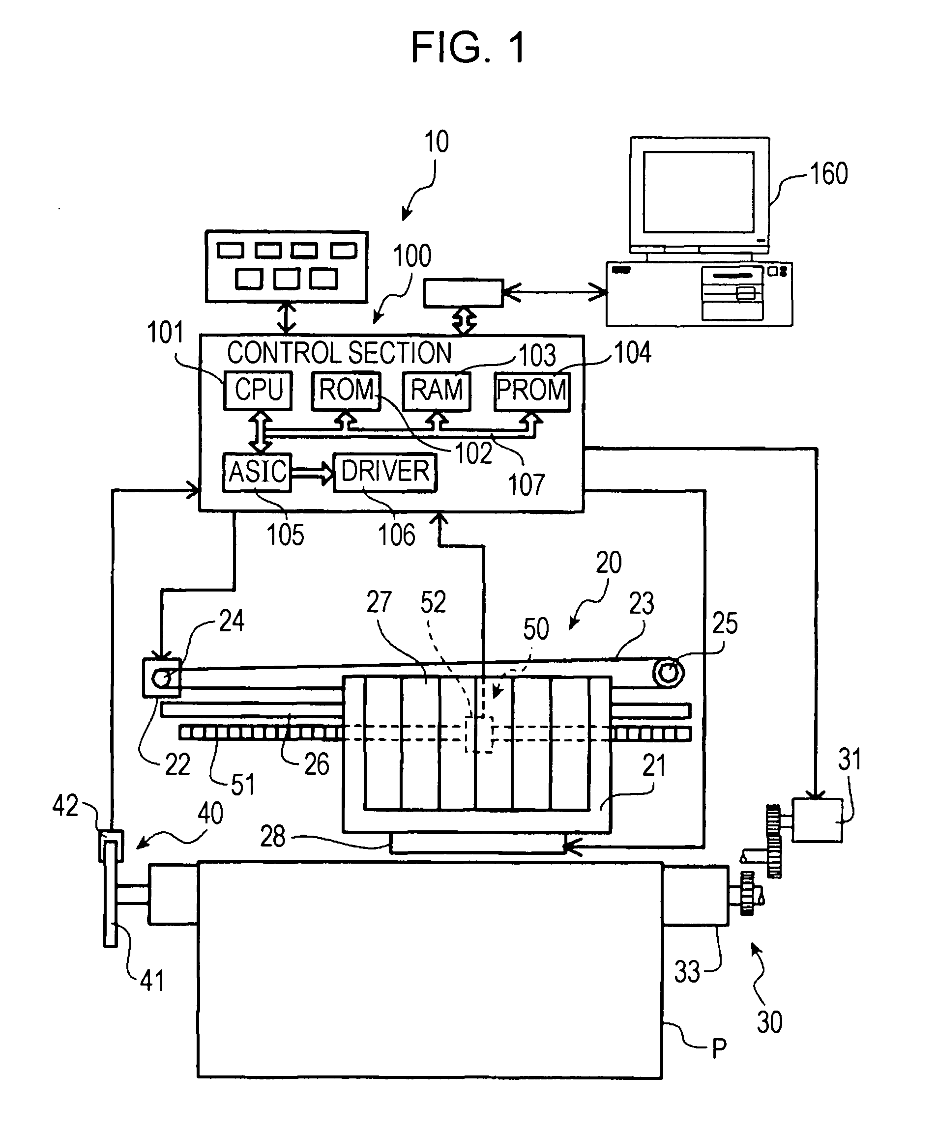
[0041]An embodiment of a printer 10 and a printing method according to the invention will be described with reference to FIG. 1 to FIG. 13. Note that the printer 10 of the present embodiment is an ink jet printer; however, the ink jet printer may be a device that employs any liquid discharging method as long as it is a device capable of printing by discharging ink.

[0042]In addition, in the following description, the lower side corresponds to a side where the printer 10 is mounted and the upper side corresponds to a side that is located a certain distance away from the side where the printer 10 is mounted. A direction in which a carriage 21, which will be described later, moves is defined as a main scanning direction (an x-coordinate direction), and a direction perpendicular to the main scanning direction and in which a print target P is transported is defined as an auxiliary scanning direction. Furthermore, a side from which the print target P is fed is defined as a paper feed side ...


PUM


Abstract

A printer that performs printing on a print target includes a motor, a storage device, a measurement control device, a corrected output power calculating device, and a corrected output power applying device. The motor applies a driving force for transporting a transport object. The storage device stores reference information relating to reference stop characteristics of the motor. The measurement control device controls driving of the motor for measuring actual stop characteristics of the motor. The corrected output power calculating device outputs a corrected output power by comparing the actual stop characteristics with the reference stop characteristics when the measurement control device controls driving of the motor. The corrected output power applying device outputs the corrected output power to the motor so that a stop condition of stopping the transport object is satisfied.

Description

BACKGROUND[0001]1. Technical Field[0002]The present invention relates to a printer and a printing method.[0003]2. Related Art[0004]Some ink jet printers include a plurality of DC motors. An ink jet printer of this type controls driving of the DC motors so as to transport a print target and to move a carriage on which a print head is mounted. In recent years, further improved print quality has been required for ink jet printers. In response to the above requirement, the size of ink droplets is becoming increasingly small. In order to direct such small ink droplets onto desired positions, it is necessary to improve the accuracy of positioning a stop position of the print target.[0005]Japanese Unexamined Patent Application Publication No. 2001-251878 describes an example which attempts to improve the accuracy of positioning a stop position of the print target. The above publication specifically describes a technology in which a speed measurement position is set at a position located a ...

Claims


Application Information

Patent Timeline
Patent Type & Authority Applications(United States)
IPC IPC(8): B41J29/38
CPCB41J29/38B41J29/02
Inventor IGARASHI, HITOSHI
Owner SEIKO EPSON CORP
Why Eureka
Try Eureka