Driving device

a technology of fastening elements and driving devices, which is applied in the direction of manufacturing tools, nailing tools, and portable percussive tools, etc., can solve the problems that devices cannot be used universally for all fastening elements and every substrate, and the energy with which the fastening element is driven into the substrate has an upper limit, so as to increase the service life of the impact-damping element, and reduce the effect of weigh

Active Publication Date: 2013-08-06
HILTI AG
View PDF9 Cites 11 Cited by
  • Summary
  • Abstract
  • Description
  • Claims
  • Application Information

AI Technical Summary

Benefits of technology

[0007]According to one aspect of the application, the energy-transfer mechanism is suitable for the purpose of transporting the energy-transfer element from the setting position in the direction toward the starting position without transferring energy to the mechanical-energy storage device. In this way it is made possible that the mechanical-energy storage device can hold and / or output energy, without moving the energy-transfer element into the setting position. The energy storage device thus can be discharged without a fastening element being driven from the device.
[0139]According to one aspect of the application, the rotational speed of the motor is reduced, while energy is stored in the mechanical-energy storage device.
[0141]According to one aspect of the application, the motor control device is suitable for supplying the motor with decreasing energy or for reducing the rotational speed of the motor while the motor is operating for storing energy in the mechanical-energy storage device.
[0148]According to one aspect of the application, the mass of the impact-damping element equals at least 15%, preferably at least 20%, especially preferred at least 25%, of the mass of the impact element. In this way, an increase in the service life of the impact-damping element with simultaneous weight savings is possible.
[0149]According to one aspect of the application, the mass of the impact-damping element equals at least 15%, preferably at least 20%, especially preferred at least 25%, of the mass of the energy-transfer element. In this way, an increase in the service life of the impact-damping element with simultaneous weight savings is likewise possible.
[0150]According to one aspect of the application, a ratio of the mass of the impact-damping element to the maximum kinetic energy of the energy-transfer element equals at least 0.15 g / J, preferably at least 0.20 g / J, especially preferred at least 0.25 g / J. In this way, an increase in the service life of the impact-damping element with simultaneous weight savings is likewise possible.

Problems solved by technology

In such devices, the energy with which the fastening element is driven into the substrate has an upper limit, so that the devices cannot be used universally for all fastening elements and every substrate.

Method used


Image

  • Driving device
  • Driving device
  • Driving device

Examples


Embodiment Construction

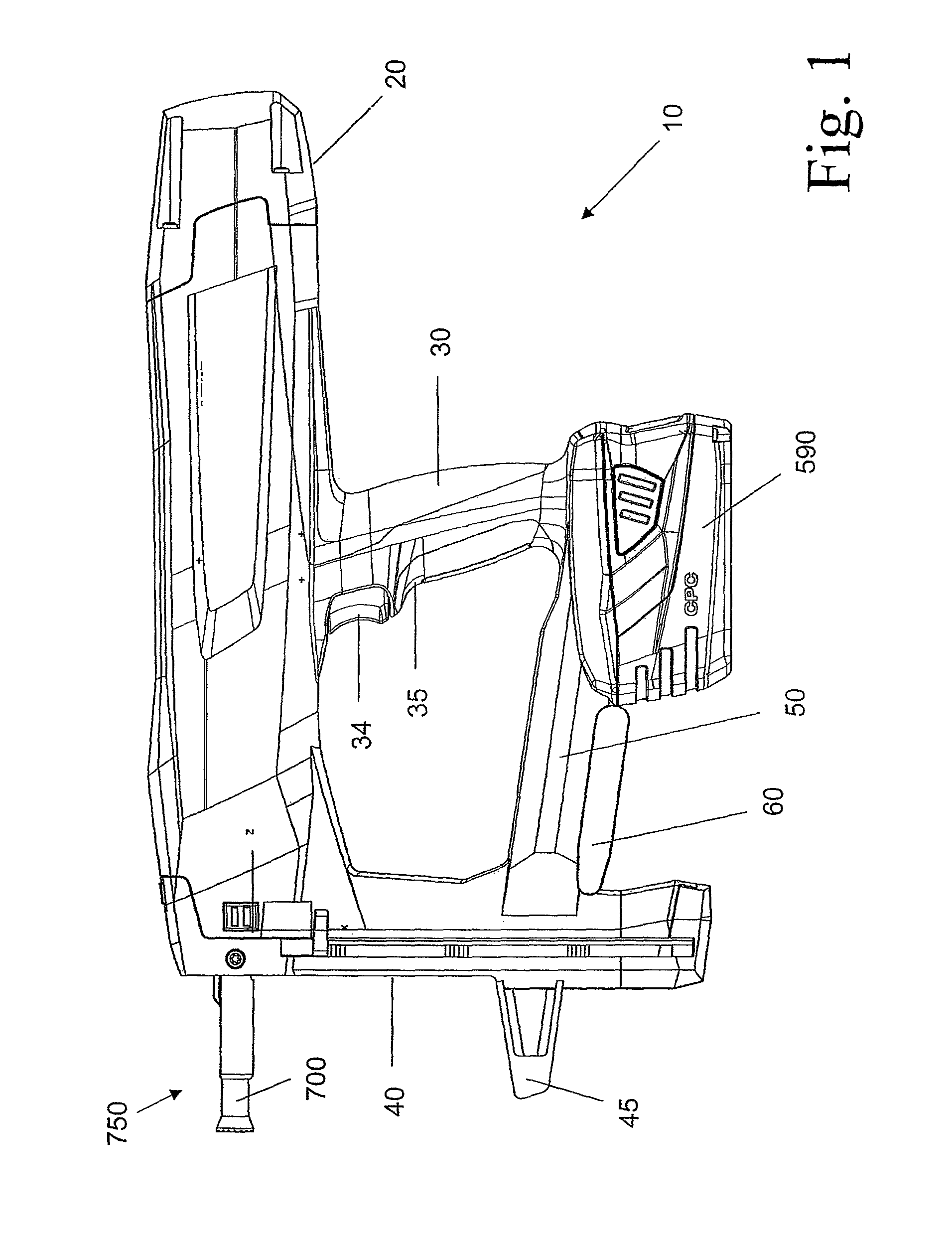
[0218]FIG. 1 shows a driving device 10 for driving a fastening element, for example, a nail or bolt, into a substrate in a side view. The driving device 10 has a not-shown energy-transfer element for transferring energy to the fastening element as well as a housing 20 in which the energy-transfer element and a similarly not-shown driving device are accommodated for transporting the energy-transfer element.

[0219]The driving device 10 further has a grip 30, a magazine 40 and a bridge 50 connecting the grip 30 to the magazine 40. The magazine is non-removable. A frame hook 60 for hanging the driving device 10 on a frame or the like and an electrical-energy storage device constructed as accumulator 590 are fastened to the bridge 50. A trigger 34 and also a grip sensor constructed as a hand switch 35 are arranged on the grip 30. The driving device 10 further has a guide channel 700 for guiding the fastening element and a contact-pressing mechanism 750 for identifying a distance of the dr...


PUM

PropertyMeasurementUnit
Shore hardnessaaaaaaaaaa
timeaaaaaaaaaa
timeaaaaaaaaaa

Abstract

According to one aspect of the application, a device for driving a fastening element into a substrate has an energy-transfer element for transferring energy to the fastening element. The energy-transfer element can move preferably between a starting position and a setting position, wherein the energy-transfer element is located, before a driving-in procedure, in the starting position and, after the driving-in procedure, in the setting position.According to another aspect of the application, the device comprises a mechanical-energy storage device for storing mechanical energy. The energy-transfer element is then suitable preferably for transferring energy from the mechanical-energy storage device to the fastening element.

Description

FIELD OF THE TECHNOLOGY[0001]The application relates to a device for driving a fastening element into a substrate.BACKGROUND OF THE INVENTION[0002]Such devices typically have a piston for transferring energy to the fastening element. The energy required for this purpose must be made available within a very short time, which is why, for example, in the case of so-called spring nailers, a spring is initially set in tension and outputs the tension energy onto the piston like an impulse during the driving-in procedure for this piston to accelerate onto the fastening element.[0003]In such devices, the energy with which the fastening element is driven into the substrate has an upper limit, so that the devices cannot be used universally for all fastening elements and every substrate. Therefore, it is desirable to make available driving devices that can transfer sufficient energy to a fastening element.BRIEF SUMMARY OF THE INTENTION[0004]According to one aspect of the application, a device ...

Claims


Application Information

Patent Timeline
Patent Type & Authority Patents(United States)
IPC IPC(8): B27F7/02
CPCB25C1/003B25C1/06B25C1/008B25C1/18B25C7/00B25D17/00
Inventor SPASOV, ROBERTMIESCHER, STEFANFIELITZ, HARALDFRANZ, KARL
Owner HILTI AG
Why Eureka
Try Eureka