Plant for bending matallic flat elements such as panels, sheets, plates or similar, bending machine for such matallic flat elements and relative bending process

a technology for bending machines and flat elements, applied in metal-working feeding devices, metal-working storage devices, positioning devices, etc., can solve the problems of inability to actually allow normal coplanar movement, complicated bending steps of bending machines, and inability to extract sheets from bending groups. to achieve the effect of facilitating manual loading and operation

Active Publication Date: 2008-09-11
TRUMPF MASCHEN AUSTRIA
View PDF2 Cites 12 Cited by
  • Summary
  • Abstract
  • Description
  • Claims
  • Application Information

AI Technical Summary

Benefits of technology

[0030]This embodiment facilitates both the manual loading operation needed by particular shaping or size

Problems solved by technology

The known bending machines present, however, several drawbacks which especially occur when there is the need to bend downwards a section of the sheet.
Indeed, in the known art, at the end of the bending downwards, the bent part is placed below the edge of the support plane and, therefore, does not actually allow the normal coplanar moving of the sheet on the support plane itself, implying, as a result, complications in the extraction phases of the sheet from the bending group.
Furthermore, to realize bending downwards with closed conformation, such as at “C”, the known bending machines require numerous and complex bending steps which, in some cases, may also require the upsetting of the sheet for the finishing of the bending.
Such operations require the manual contribution of highly specialized operators and lengthy and onerous implementation times, no

Method used


Image

  • Plant for bending matallic flat elements such as panels, sheets, plates or similar, bending machine for such matallic flat elements and relative bending process
  • Plant for bending matallic flat elements such as panels, sheets, plates or similar, bending machine for such matallic flat elements and relative bending process
  • Plant for bending matallic flat elements such as panels, sheets, plates or similar, bending machine for such matallic flat elements and relative bending process

Examples


Embodiment Construction

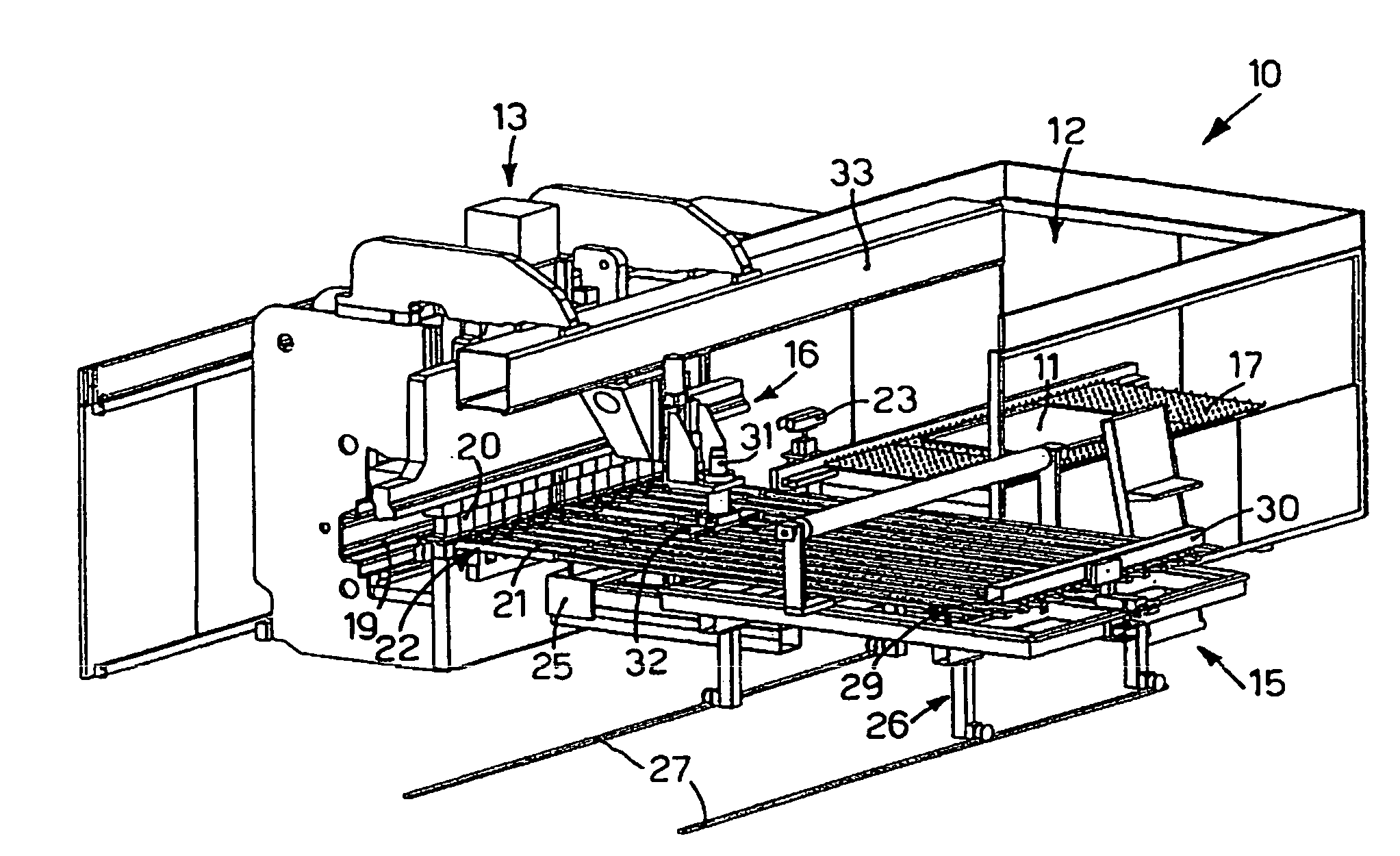
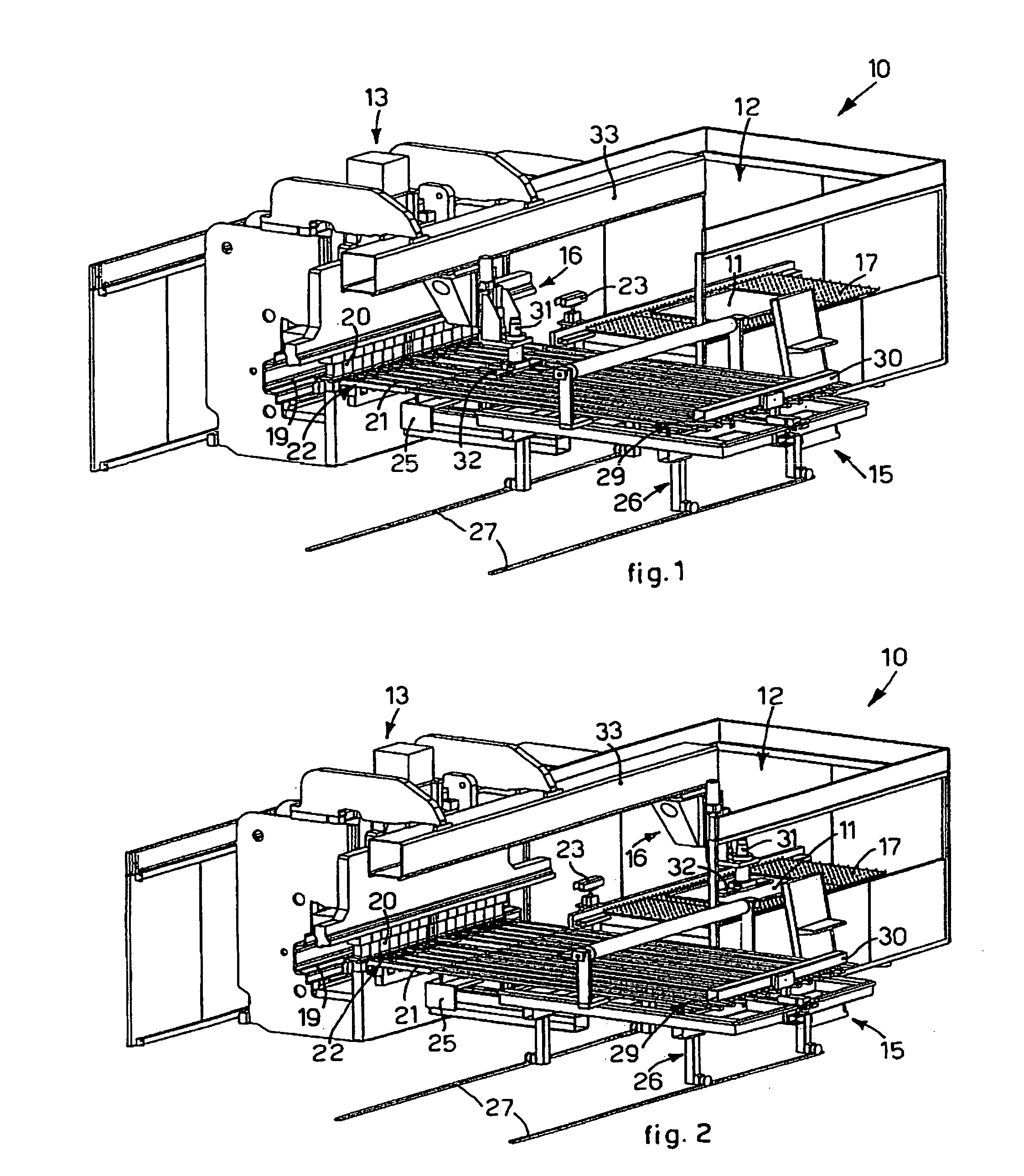
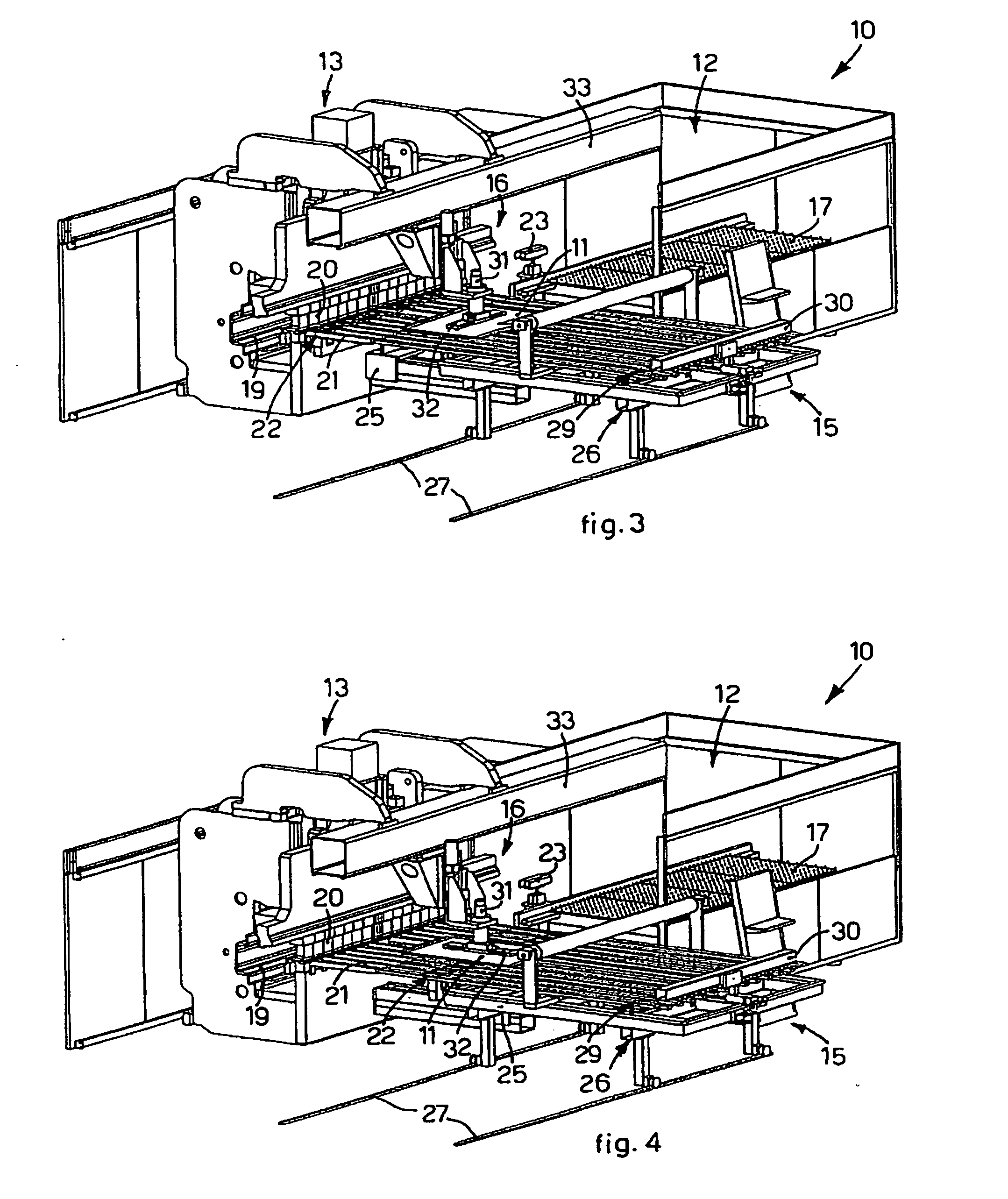
[0045]With reference to the attached figure, it is shown as a whole a plant 10 for bending metallic flat elements, in the specific case a sheet 11.

[0046]In particular, the plant 10 includes a loading station 12, aligned to which there is a bending machine 13, downstream of which an evacuation station 15 is provided.

[0047]The plant 10 according to the invention also comprises a translation member 16 which transports the sheet 11 from the loading station 12 to the bending machine 13, and sets it out in the correct position of bending.

[0048]The loading station 12 includes substantially a positioning bench 17, on which the sheets 11 to bend are arranged.

[0049]The bending machine 13 includes at least one bending group 19, a blank holder arm 20 and a support plane 21, substantially horizontal and associated with a plurality of sucker feeding organs 22 which hold the sheet 11 from the bottom to keep it sticking to the support plane 21. Such feeding organs 22 are also movable with respect t...


PUM

PropertyMeasurementUnit
Metallic bondaaaaaaaaaa

Abstract

Plant (10) for bending metallic flat elements (11) including a bending machine (13) provided with a support plane (21) on which the metallic flat element (11) to be bent is positioned, a bending group (19) which bends, upwardly or downwards, a section of the metallic flat element (11), and a sucker feeding group (22) associated with the support plane (21) for selectively feeding the metallic flat element (11) to the bending group (19). The feeding group includes one or more sucker organs (22) aligned in a direction substantially transverse to the metallic flat element (11) to be bent and placed, in the rest position, below the support plane (21), to lift the metallic flat element (11) of a given height (D) from the edge of the support plane (21), after the bending has been carried out.

Description

FIELD OF THE INVENTION[0001]The present invention refers to a plant for bending, and eventually shaping, even in a radial type, metallic flat elements, such as panels, sheets, plates and the like, in order to obtain a shaped element according to a predetermined drawing or project. In particular, the plant in accordance with the present invention includes at least one bending machine configured in such a way as to carry out, in the same way, bending directed upwardly or downwards. The present invention also relates to a bending, and in case shaping, process to obtain from said metallic flat elements an element shaped in a prefixed manner.STATE OF THE ART[0002]They are known automatic plants through which a metallic flat element of the deformable type, for example a panel or a sheet, is bent in order to obtain an element shaped according to a predetermined project scheme.[0003]The known plants include, arranged substantially one aligned to the other, a loading station on which the she...

Claims


Application Information

Patent Timeline
IPC IPC(8): B21D5/04B21D43/11
CPCB21D43/18B21D5/04B21D5/045
Inventor CODATTO, ANTONIO
Owner TRUMPF MASCHEN AUSTRIA
Why Eureka
Try Eureka