Hydraulic caliper brake assembly for a bicycle

a technology of hydraulic caliper and brake assembly, which is applied in the direction of cycle brakes, cycle brakes, and fluid actuated brakes, can solve the problems of unadjustable hydraulic pressure for opening the check valve, inability to meet the requirements of various environments or riders, and easy expansion of oil circuits, etc., to achieve a better heat dissipation effect, simple oil circuit, and a bigger braking force

Inactive Publication Date: 2011-07-05
ASHIMA LTD
View PDF16 Cites 16 Cited by
  • Summary
  • Abstract
  • Description
  • Claims
  • Application Information

AI Technical Summary

Benefits of technology

[0004]Accordingly, the object of the present invention is to provide a hydraulic caliper brake assembly for a bicycle having a simple oil circuit with a better heat dissipation effect. Furthermore, the hydraulic pressure is adjustable and the speed reduction stage and emergency braking stage are divided in the present invention and there is no dead travel “lost motion” where the rider displaces the lever further with no subsequent increase in the braking force. Additionally a bigger braking force can be achieved without increasing the piston bore size and therefore the size / mass of the system.
[0007]Moreover, two outer oil tubes are installed at an outer side of the caliper body for communicating the first chamber and the second chamber corresponding to the first chamber. Not only controlling the actions at two sides at the same time, by installation of the outer oil tubes, the inner oil circuit in the caliper body can be simplified and more importantly can better dissipate the heat in the fluid. Also as when only the small piston is used it creates an air cooling effect as the surface of the brake pad is clear of the bigger piston. Additionally when comparing to a conventional brake system with the same sized main bore the max braking force of the system is increased in the emergency braking stage as the total piston area is equal to the small piston area plus the big piston area. Hence you can have the benefit of higher braking performance but in the same space / envelope of prior art.

Problems solved by technology

However it still has the problem that a greater braking force is provided so that it is possible to over brake such that the rider can be thrown over the front wheel or the wheels are locked such that the rider losses control, potentially leading to serious injury.
Additional due to heat generated during prolonged braking, i.e. holding the bike at constant speed during a long hill descent, the oil tends to expand leading brake drag issues once the brake lever has been released.
In the worst case this heat can vaporize the oil leading to a total loss of braking.
The pressure reduction cylinder indeed offers an improvement over prior art, but has a couple of drawbacks: 1. Dead point where the rider wants more power but only displaces the inner relief piston.
The hydraulic pressure for opening the check valve is un-adjustable and can not match the requirement of various environments or riders preference.
It doesn't address the problem of heat dissipation.
Also due to the relative large size of the piston the initial brake forces are still high.

Method used


Image

  • Hydraulic caliper brake assembly for a bicycle
  • Hydraulic caliper brake assembly for a bicycle
  • Hydraulic caliper brake assembly for a bicycle

Examples


Embodiment Construction

[0014]In order that those skilled in the art can further understand the present invention, a description will be provided in the following in details. However, these descriptions and the appended drawings are only used to cause those skilled in the art to understand the objects, features, and characteristics of the present invention, but not to be used to confine the scope and spirit of the present invention defined in the appended claims.

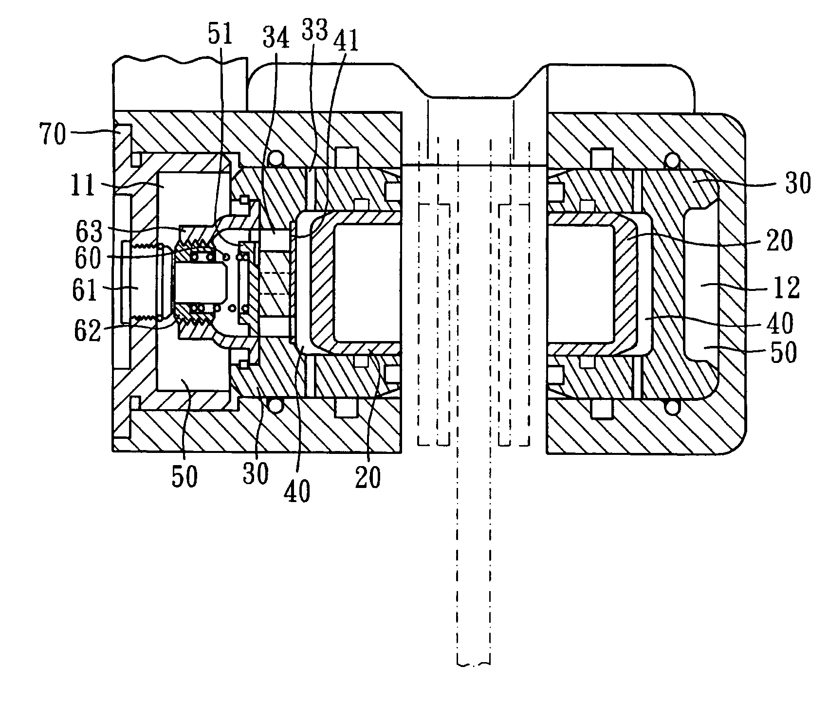
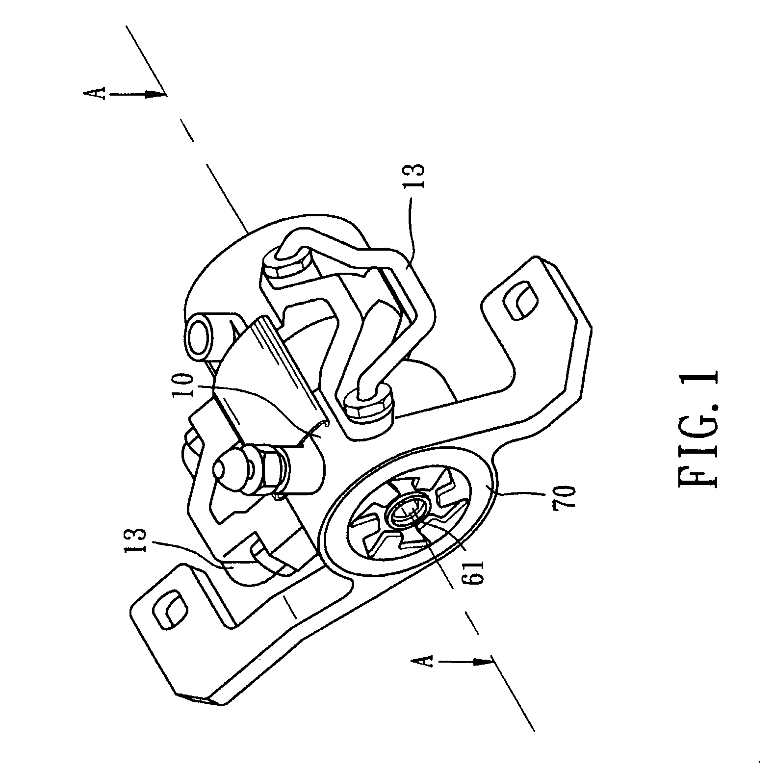
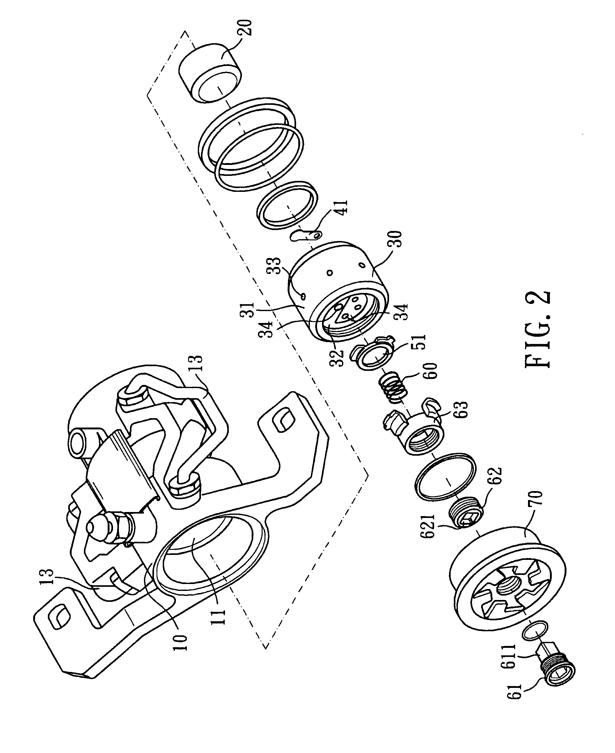
[0015]With referring to FIGS. 1 and 2, a hydraulic caliper brake assembly for a bicycle according to the present invention is illustrated. The present invention has the following elements.

[0016]A caliper body 10 is installed to a bicycle frame or a bi-forked assembly of a bicycle and is assembled to a brake pad (not shown) so as to brake the bicycle with the brake disk (not shown).

[0017]A first chamber 11 is installed in the caliper body 10.

[0018]A first piston 20 is installed in the first chamber 11 and has a round cylinder shape.

[0019]A second pi...


PUM


Abstract

A hydraulic caliper brake assembly for a bicycle comprises a caliper body; a first chamber installed in the caliper body; a first piston installed in the first chamber; a second piston installed in the first chamber; an inner chamber formed between the first piston and the second piston for receiving brake oil; an outer chamber installed between the second piston and the caliper body for receiving brake oil; and an outer valve installed in the second piston for switching flowing of the brake oil between the inner chamber and outer chamber. When a small force is applied, the brake oil will flow into the inner chamber; by closing the outer valve, the first piston is pushed to have the effect of speed reduction; when the braking force is increased, by opening the outer valve, the second piston is pushed to have the effect of emergent braking.

Description

FIELD OF THE INVENTION[0001]The present invention relates to bicycle parts, and particularly to a hydraulic caliper brake assembly for a bicycle which has a simple oil circuit that permits two stages of braking force with a better heat dissipation effect. Furthermore, the hydraulic pressure to switch between those two stages is adjustable so that the speed reduction stage and emergency braking stage are divided in the present invention.BACKGROUND OF THE INVENTION[0002]A brake is an important safety device for a bicycle. The brake uses friction force to achieve the effect of speed reduction. In the brake system, by Pascal principle, brake oil serves to transfer the brake force from the brake lever to a hydraulic pressure caliper to push the piston and the brake pads so as to compress the brake disk to have the effect of braking. The hydraulic pressure brake system has the following advantages: 1. The function of the brake is not so affected by weather, environment, or temperature, ho...

Claims


Application Information

Patent Timeline
Patent Type & Authority Patents(United States)
IPC IPC(8): F16D55/18
CPCF16D65/18F16D2121/02F16D2127/007
Inventor MOORE, WAYNE-IAN
Owner ASHIMA LTD
Why Eureka
Try Eureka