Method and apparatus for supplying process liquid for machine tool

a technology of process liquid and machine tool, which is applied in the direction of special dispensing means, multiple way valves, feed/discharge of settling tanks, etc., can solve the problems of comparatively large pump consumption power, and achieve the effect of lowering the waste power consumption of the pump, lowering the discharge pressure of the pump, and lowering the consumption power of the pump

Inactive Publication Date: 2005-09-06
HORKOS
View PDF19 Cites 20 Cited by
  • Summary
  • Abstract
  • Description
  • Claims
  • Application Information

AI Technical Summary

Benefits of technology

[0019]According to the above-described apparatus, after the pump discharges process liquid of one-time supply volume flows out, the process liquid in the main tank is transferred into the sub tank until commencement of the next supply. At this time, a contribution is made to the lowering in waste power consumption of the pump wherein the discharge rate Q of the pump is smaller than the maximum flow rate of the process liquid of one-time supply volume.
[0020]In addition, the sub tank is installed so that its bottom is higher by approximately 0.5 through 10 meters than the upper surface of the workrest, wherein when the pump transfers process liquid from the main tank to the sub tank, the discharge pressure may be reduced to, for example, approximately one-tenth of that of the prior arts. In this case, the process liquid can be smoothly supplied to necessary points for which the process liquid must be supplied. And, at this time, a lowering in the discharge pressure of the pump can greatly contribute to a lowering in the consumption power of the pump.

Problems solved by technology

Therefore, the consumption power of the pump becomes comparatively large.

Method used


Image

  • Method and apparatus for supplying process liquid for machine tool
  • Method and apparatus for supplying process liquid for machine tool
  • Method and apparatus for supplying process liquid for machine tool

Examples


Embodiment Construction

[0025]A detailed description is given of the present invention with reference to the accompanying drawings.

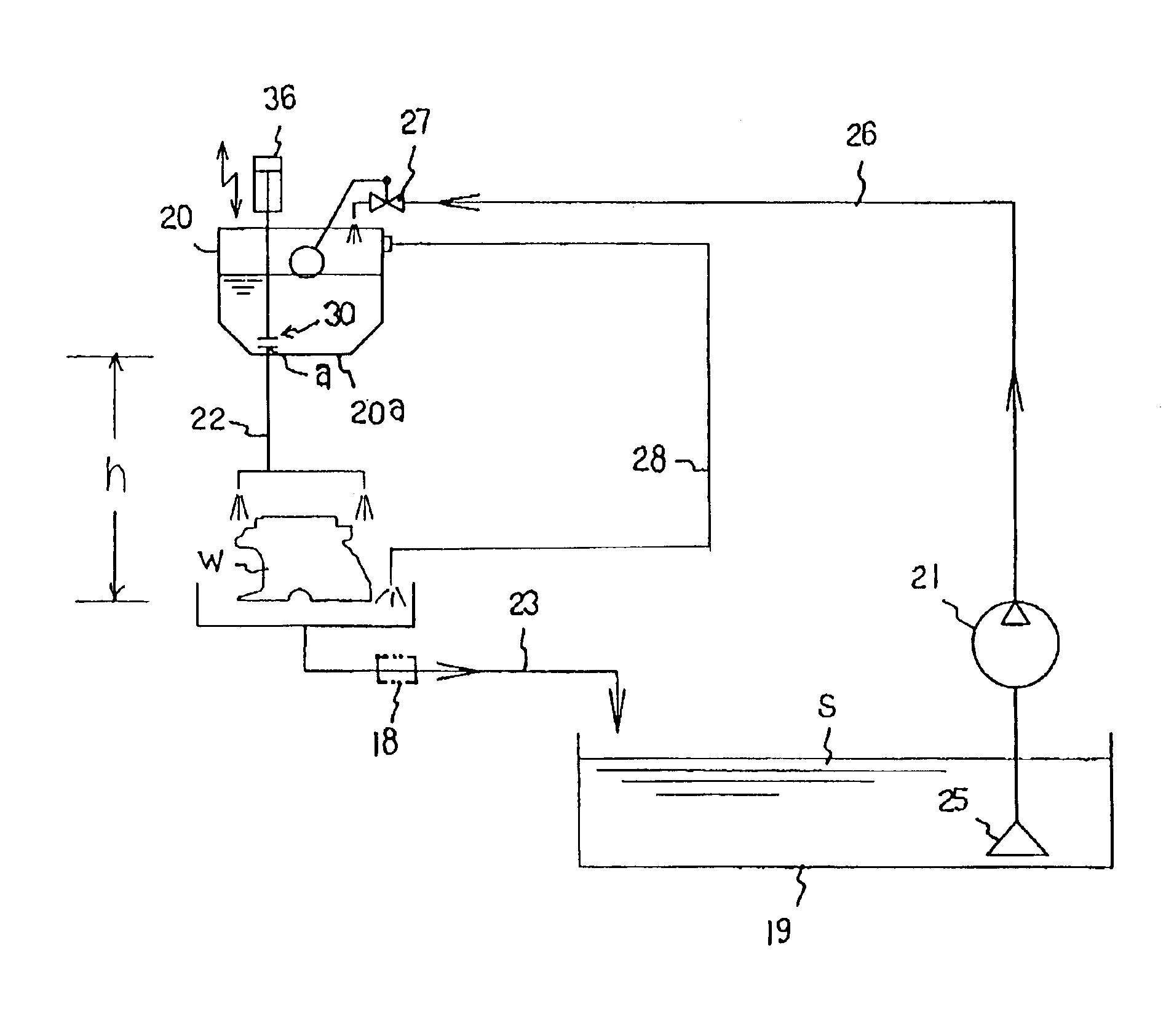
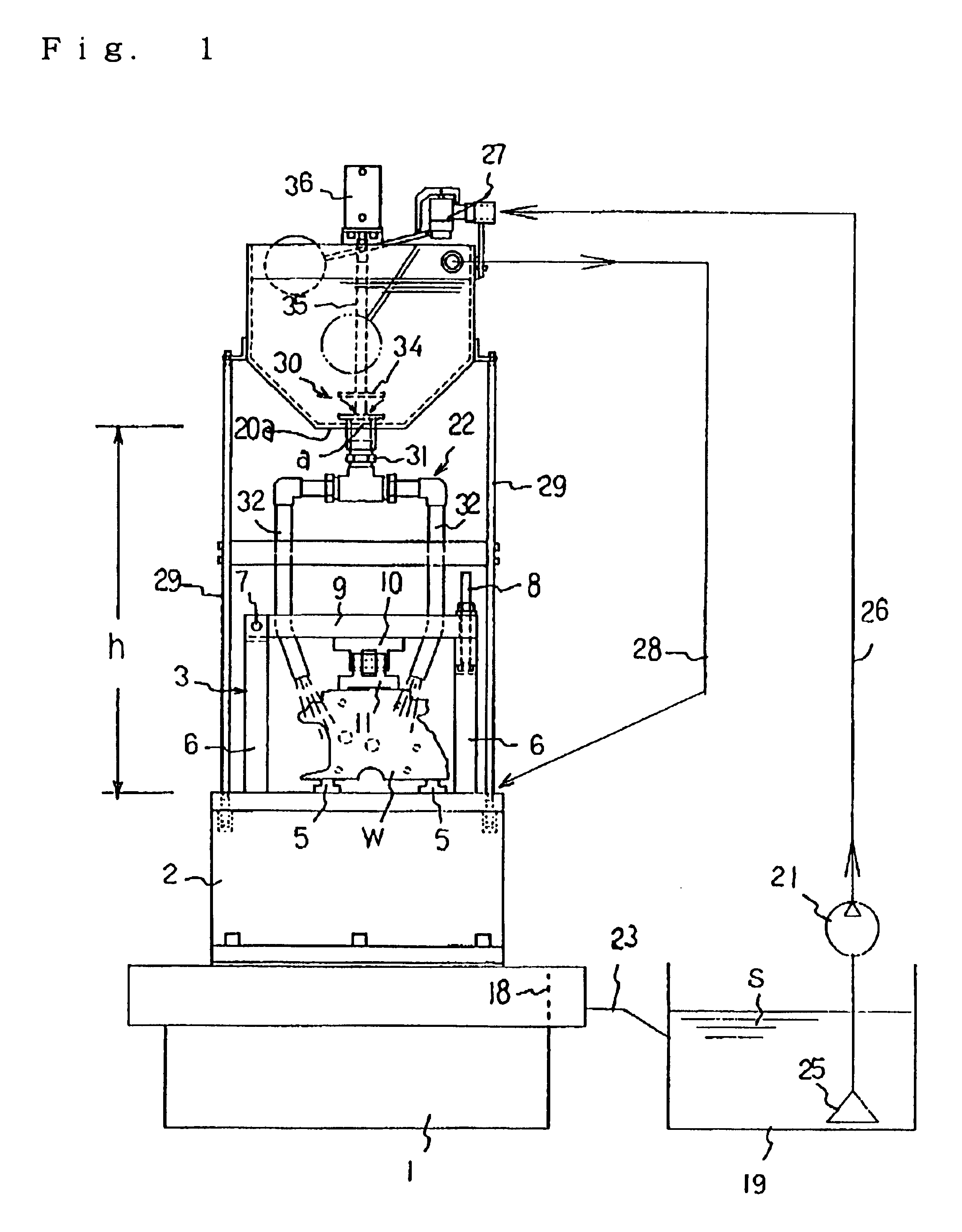
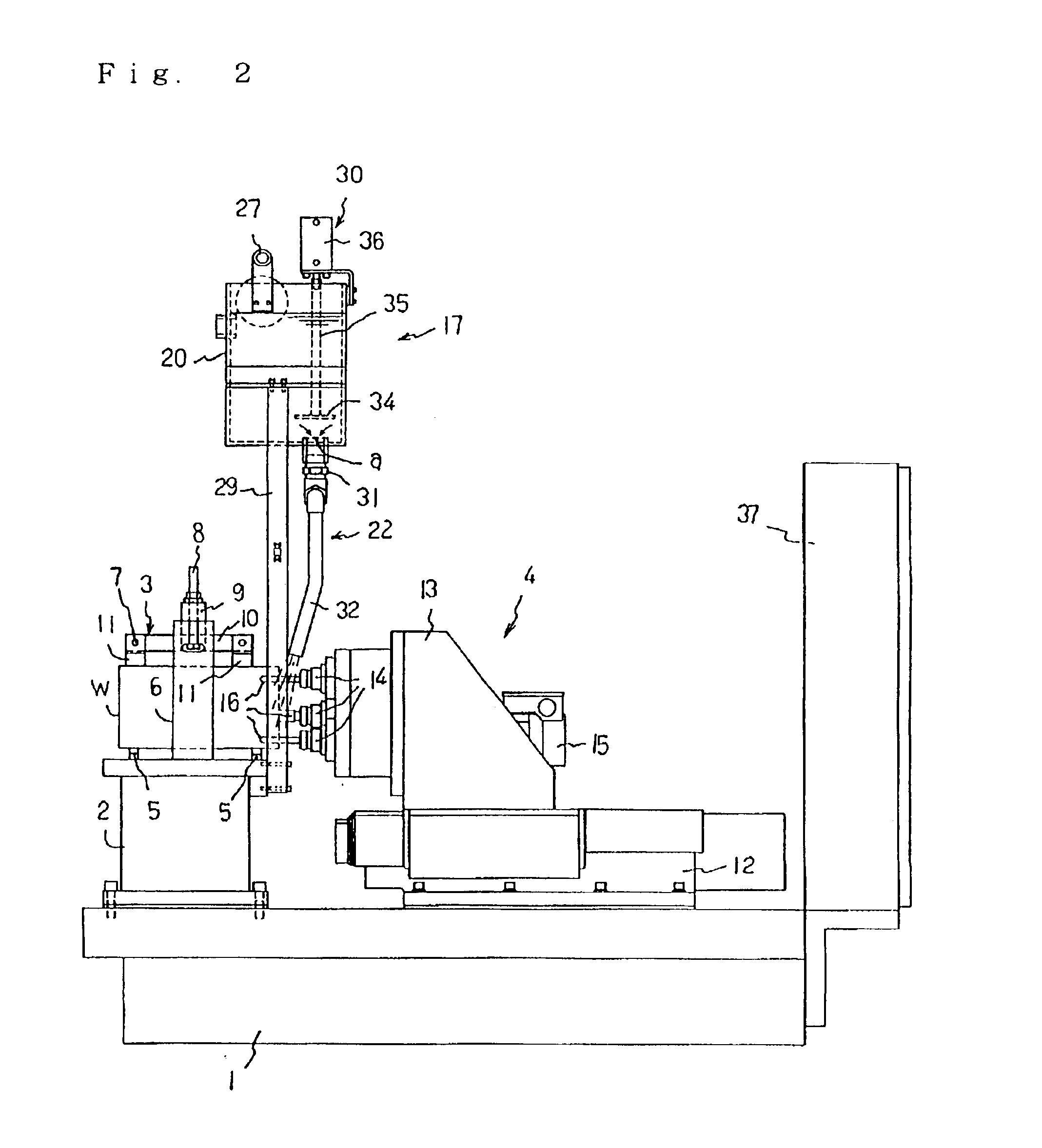
[0026]FIG. 1 through FIG. 3 show an apparatus for supplying process liquid for a machine tool according to the invention, wherein FIG. 1 is a front elevation view thereof with a part omitted, FIG. 2 is a side elevation view thereof, and FIG. 3 is a view showing the process liquid supplying system thereof.

[0027]In these drawings, reference number 1 denotes a foundation base. A workrest 2 is fixed on the foundation base 1. A fixture (jig) 3 is provided to fix a workpiece w on the workrest 2. Workpiece machining means 4 is formed on the foundation base 1.

[0028]The above-described workrest 2 is structured so that it fixes receiver members 5 and 5 which support the workpiece w on the upper surface of the workrest 2, collects process liquid s flown on the workpiece w and the upper surface of the workrest 2 by a gravity action, and causes the process liquid to flow into another place....


PUM

PropertyMeasurementUnit
distanceaaaaaaaaaa
diameteraaaaaaaaaa
diameteraaaaaaaaaa

Abstract

The present invention provides a method and apparatus for supplying process liquid s for a machine tool, which are able to reduce the consumption power and power factor of the pump 21 to a large extent in comparison with prior arts while maintaining the effects of process liquid s according to prior arts. The invention is embodied so that process liquid s such as coolant or cleaning fluid is supplied to necessary points by causing the process liquid s to flow down, which is stored in a sub tank 20 installed at a suitable height in a machine tool, by a gravity action when intermittently supplying the process liquid s such as coolant or cleaning fluid to the necessary points such as a workrest 2 and a workpiece w fixed thereon; the supplied process liquid s is collected into a main tank 19 on the other hand; and the process liquid s stored in the main tank 19 is transferred into the sub tank 20 by the pump 21.

Description

TECHNICAL FIELD[0001]The present invention relates to a method and apparatus for supplying process liquid for a machine tool. Herein, the process liquid includes coolant and cleaning fluid.BACKGROUND ART[0002]FIG. 4 shows an example of a prior art process liquid supplying apparatus for a machine tool. The prior art process liquid supplying apparatus is provided with a tank 19 for collecting a process liquid s, which is supplied to points, for which it is necessary to supply a process liquid, such as a workrest and a workpiece w fixed thereon, a pump 21 for transferring the process liquid s in the tank 19, and process liquid passage means 22a for supplying the process liquid s transferred from the pump 21 to points, for which it is necessary to supply the process liquid, at an optional time.[0003]Cutting chips produced through machining by a machine tool are adhered to or accumulated on a workpiece w and workrest. In order to accurately fix a next workpiece w on the workrest, it is n...

Claims


Application Information

Patent Timeline
Patent Type & Authority Patents(United States)
IPC IPC(8): B23Q11/10B23Q11/12
CPCB23Q11/10B23Q39/023Y10T409/304032Y10S29/094B23Q11/005B23Q11/1076Y10T137/4245Y10T137/85978Y10T137/7439Y10T137/0318Y10T137/7287Y10T137/86187Y10T137/87684Y02P70/10
Inventor SUGATA, SHINSUKEMAKIYAMA, TADASHIMIYATA, TAKANORI
Owner HORKOS
Why Eureka
Try Eureka