
Seat belt retractor for the safety belt of a motor vehicle

a technology for safety belts and motor vehicles, which is applied in the direction of safety belts, pedestrian/occupant safety arrangements, vehicular safety arrangements, etc., can solve the problems of substantial deviation of the rotation angle, the beginning of the high load limiting level is dependent on and the load limiting element does not work independently of each other. , to achieve the effect of high precision

Active Publication Date: 2014-05-20
AUTOLIV DEV AB
View PDF12 Cites 5 Cited by
  • Summary
  • Abstract
  • Description
  • Claims
  • Application Information

AI Technical Summary

Benefits of technology

The invention is a seat belt retractor with two load limiting elements that act independently during each phase of load limiting. The load limiting levels can be individually determined by designing each load limiting element, and a modular system allows for different load limiting characteristics without needing to modify other components. The load limiting level is switched by a connecting element that is connected to the load limiting elements and directly results from the load limited belt webbing extraction movement. This allows for a high precision in the switching process. Overall, the invention provides improved safety and flexibility for seat belt retractors.

Problems solved by technology

There is the general problem about rear seats that the distance available for the forward displacement of children or smaller adults, as for example the 5th percentile-sized woman in a frontal collision, shall be utilized to the maximum, whereas for the heavy passenger the same safety belt must prevent a maximum belt webbing extraction length from being exceeded in a collision.
However, it is a disadvantage of the proposed seat belt retractor that the progressive load limiting characteristic is achieved by the load limiting elements being activated simultaneously, and that the load limiting elements do not work independent of each other.
Furthermore, the beginning of the high load limiting level depends on the time when the threaded bushing is pulled to the dead stop position.
As the available installation space is highly limited, it is desirable to use a thread having a pitch as small as possible resulting in the disadvantage that even minor deviations of the distance lead to substantial deviations of the rotation angle, at which the load limiting level is switched, from the predetermined rotation angle.

Method used


Image

  • Seat belt retractor for the safety belt of a motor vehicle
  • Seat belt retractor for the safety belt of a motor vehicle
  • Seat belt retractor for the safety belt of a motor vehicle

Examples


Embodiment Construction

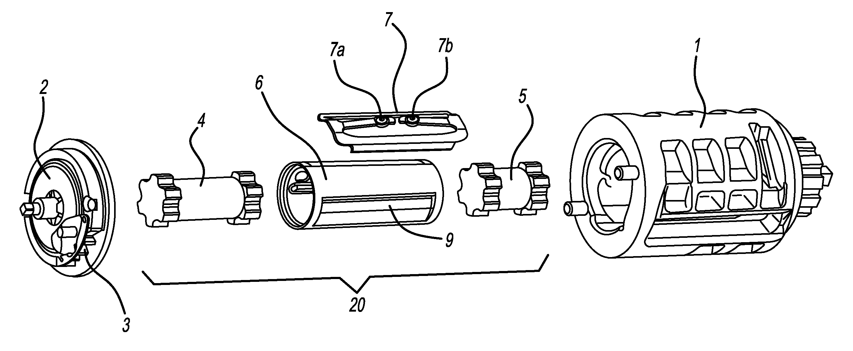
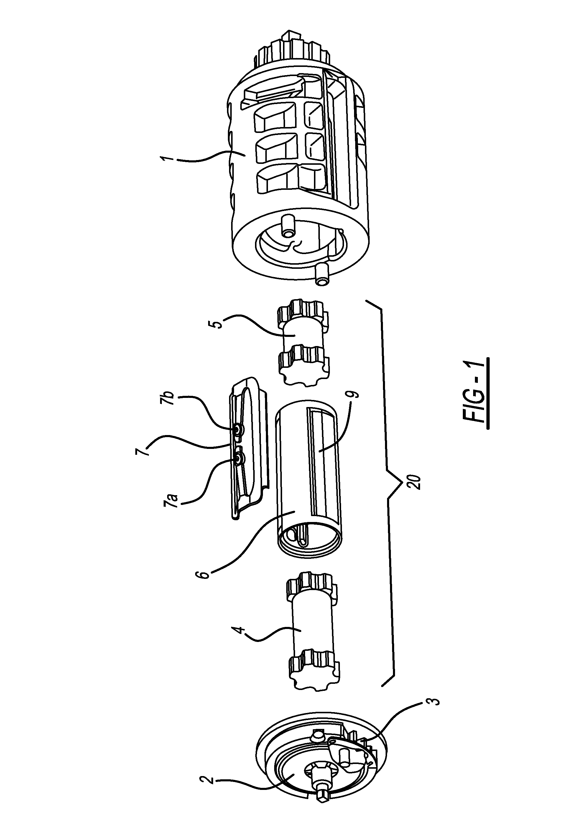
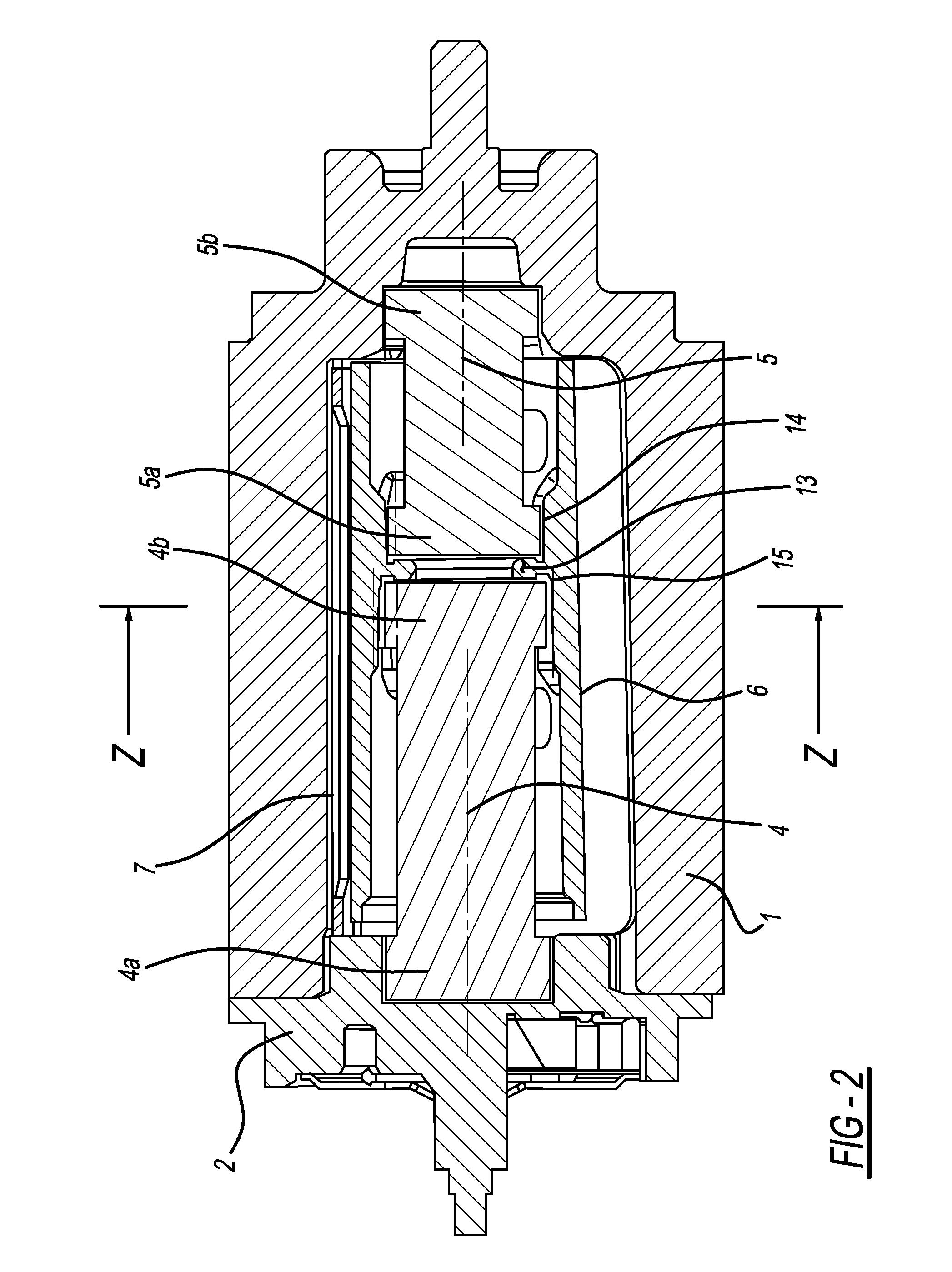
[0019]FIG. 1 shows a seat belt retractor according to the invention comprising a belt shaft 1, a profile head 2 and a load limiting device 20 located between the belt shaft 1 and the profile head 2. The belt shaft 1 is rotatably mounted in a vehicle-fixed frame (not shown), in which frame a toothing is provided, in which the profile head 2 can be locked via a locking pawl 3 mounted on the profile head 2. A safety belt (not shown) can be wound up onto the belt shaft 1, which safety belt serves for restraining the passenger in the motor vehicle. During an accident, at first, the profile head 2 is locked via the locking pawl 3. At a further increase of the belt force during the forward displacement of the passenger, the load limiting device 20 enables the belt shaft 1 to undergo a load limited rotation in the belt webbing extraction direction when a predetermined load limiting level is exceeded thereby limiting belt loads acting on the restrained passenger.

[0020]The load limiting devic...


PUM


Abstract

A seat belt retractor for a safety belt of a motor vehicle having a belt shaft (1) rotatably mounted in a frame, a profile head (2) lockable in relation to the frame, a load limiting device (20) located between the profile head (2) and the belt shaft (1) for enabling the belt shaft (1) to undergo a load limited rotation in the belt webbing extraction direction (A) with the profile head (2) being locked and a load limiting level predetermined by the load limiting device (20) being exceeded.

Description

CROSS REFERENCE TO RELATED APPLICATIONS[0001]This application claims priority to German Application No. 10 2009 024292.9, filed Jun. 5, 2009 and PCT / EP2010 / 003268, filed May 28, 2010.FIELD OF THE INVENTION[0002]The invention relates to a seat belt retractor for a safety belt of a motor vehicle.BACKGROUND OF THE INVENTION[0003]Generic seat belt retractors are used for example in motor vehicles for the safety belts of the rear seats. There is the general problem about rear seats that the distance available for the forward displacement of children or smaller adults, as for example the 5th percentile-sized woman in a frontal collision, shall be utilized to the maximum, whereas for the heavy passenger the same safety belt must prevent a maximum belt webbing extraction length from being exceeded in a collision. Therefore, the load limiting device of such a seat belt retractor generally comprises two load limiting elements, by the time-shifted activation of which the load limiting level ca...

Claims


Application Information

Patent Timeline
Patent Type & Authority Patents(United States)
IPC IPC(8): B65H75/48
CPCB60R2022/287B60R22/3413
Inventor DAHLQUIST, BENGTRYDSMO, ERIK ARTHURWIGSTROM, FREDRIK
Owner AUTOLIV DEV AB
Learn More