
Low frequency diversity antenna system

Active Publication Date: 2014-05-20
MALIKIE INNOVATIONS LTD
View PDF15 Cites 18 Cited by
  • Summary
  • Abstract
  • Description
  • Claims
  • Application Information

AI Technical Summary

Problems solved by technology

The design and implementation of multiple antennas with independent transmit and receive paths on a mobile terminal introduces significant design challenges for compact devices that operate in a low frequency range.
It is typically a challenge to achieve low correlation and high isolation in mobile terminals of compact size and limited internal space for components.

Method used


Image

  • Low frequency diversity antenna system
  • Low frequency diversity antenna system
  • Low frequency diversity antenna system

Examples


Embodiment Construction

[0013]It should be understood at the outset that although an illustrative implementation of one or more embodiments are provided below, the description is not to be considered as limiting the scope of the embodiments described herein. The disclosure may be implemented using any number of techniques, whether currently known or in existence. The disclosure should in no way be limited to the illustrative implementations, drawings, and techniques illustrated and described herein, which may be modified within the scope of the appended claims along with a full scope of equivalence. It should be appreciated that for simplicity and clarity of illustration, where considered appropriate, the reference numerals may be repeated among the figures to indicate corresponding or analogous elements.

[0014]According to an illustrative embodiment, a mobile communication device comprises a plurality of antennas coupled to a single planar dielectric substrate. Each antenna comprises a plurality of radiati...


PUM


Abstract

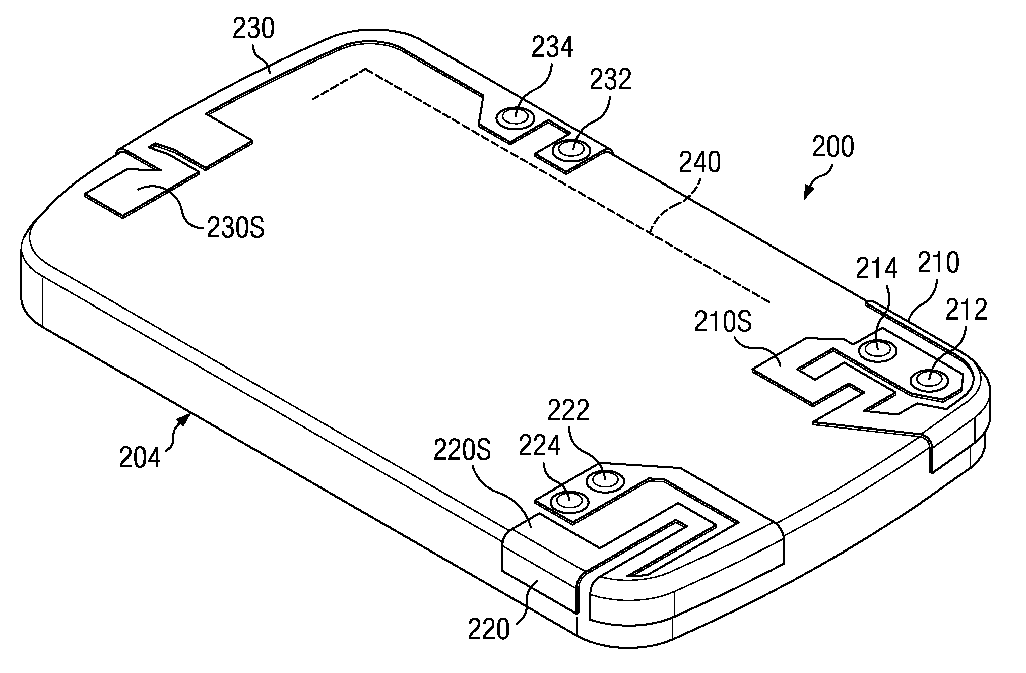
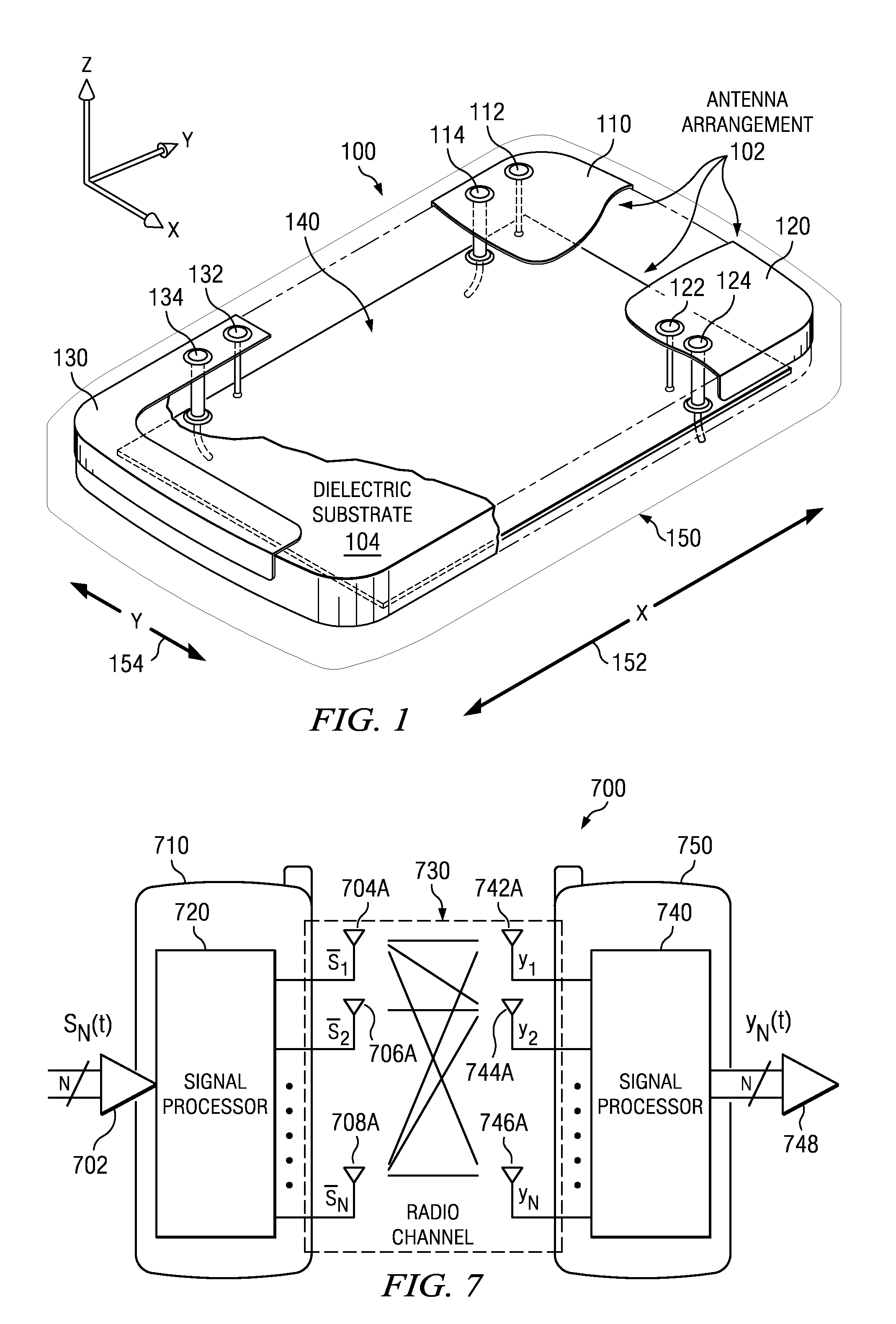
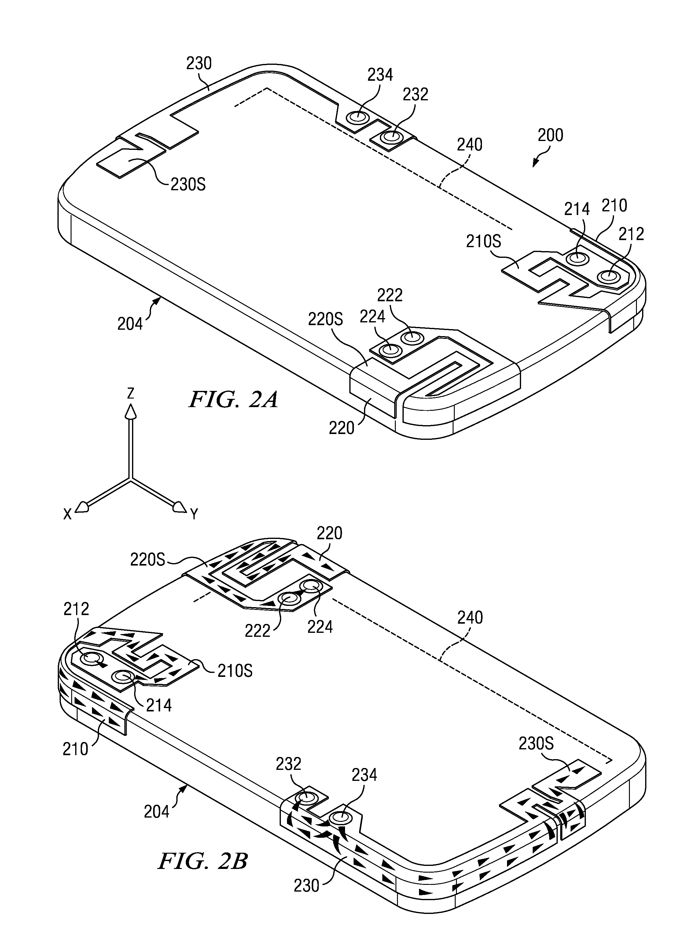
A diversity antenna system that operates within a low frequency band ranging from 700 Megahertz is disclosed. A plurality of antennas are folded onto a single printed circuit in a meander pattern configuration. Each antenna has an independent feed port and ground pin. The plurality of antennas are configured within a compact mobile phone space to produce a high isolation and low correlation at resonating frequencies within the 700 Megahertz frequency band.

Description

BACKGROUND[0001]1. Technical Field[0002]This disclosure relates to a diversity antenna arrangement for a mobile terminal and more specifically to the design and implementation of a diversity antenna system that operates within a fundamental resonant low frequency band of 700 Megahertz (MHz).[0003]2. Description of the Related Art[0004]The design and implementation of multiple antennas with independent transmit and receive paths on a mobile terminal introduces significant design challenges for compact devices that operate in a low frequency range. The Long Term Evolution frequency spectrum or range supports a number of frequency bands, including a 746-787 MHz band, 882-960 MHz band, 1710-2155 MHz band, and 2500-2700 MHz frequency band. In the low frequency bands, such as frequency bands, the design of multiple antennas on a mobile terminal, such as, the 746-787 MHz band mobile cellular handsets, smart phone's, hand-held computers, and other such devices known to one skilled in the ar...

Claims


Application Information

Patent Timeline
Patent Type & Authority Patents(United States)
IPC IPC(8): H01Q1/24
CPCH01Q21/28H01Q9/0421H01Q1/243H01Q1/521
Inventor RAO, QINJIANG
Owner MALIKIE INNOVATIONS LTD
Learn More