

Chassis-excited antenna apparatus and methods
a technology of antenna and chassis, applied in the direction of antennas, antenna supports/mountings, radiating elements structural forms, etc., can solve the problems of limiting the flexibility of device layout implementation, degrading antenna performance, and often inadequate antenna solutions for the above thin devices with metal housings and/or chassis
- Summary
- Abstract
- Description
- Claims
- Application Information
AI Technical Summary
Benefits of technology
Problems solved by technology
Method used
Image

Examples
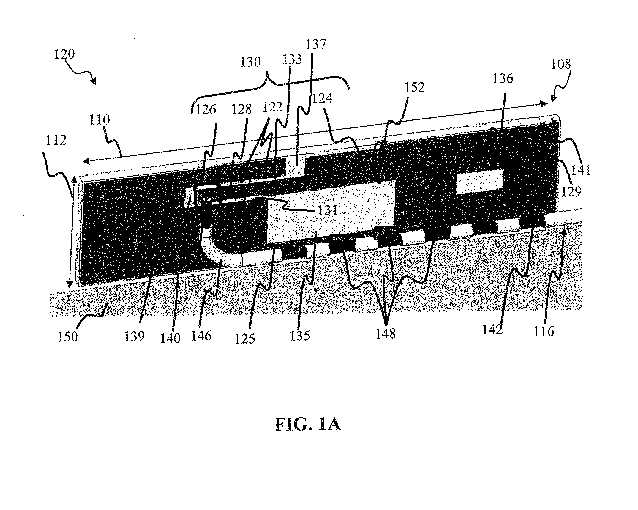
embodiment 120
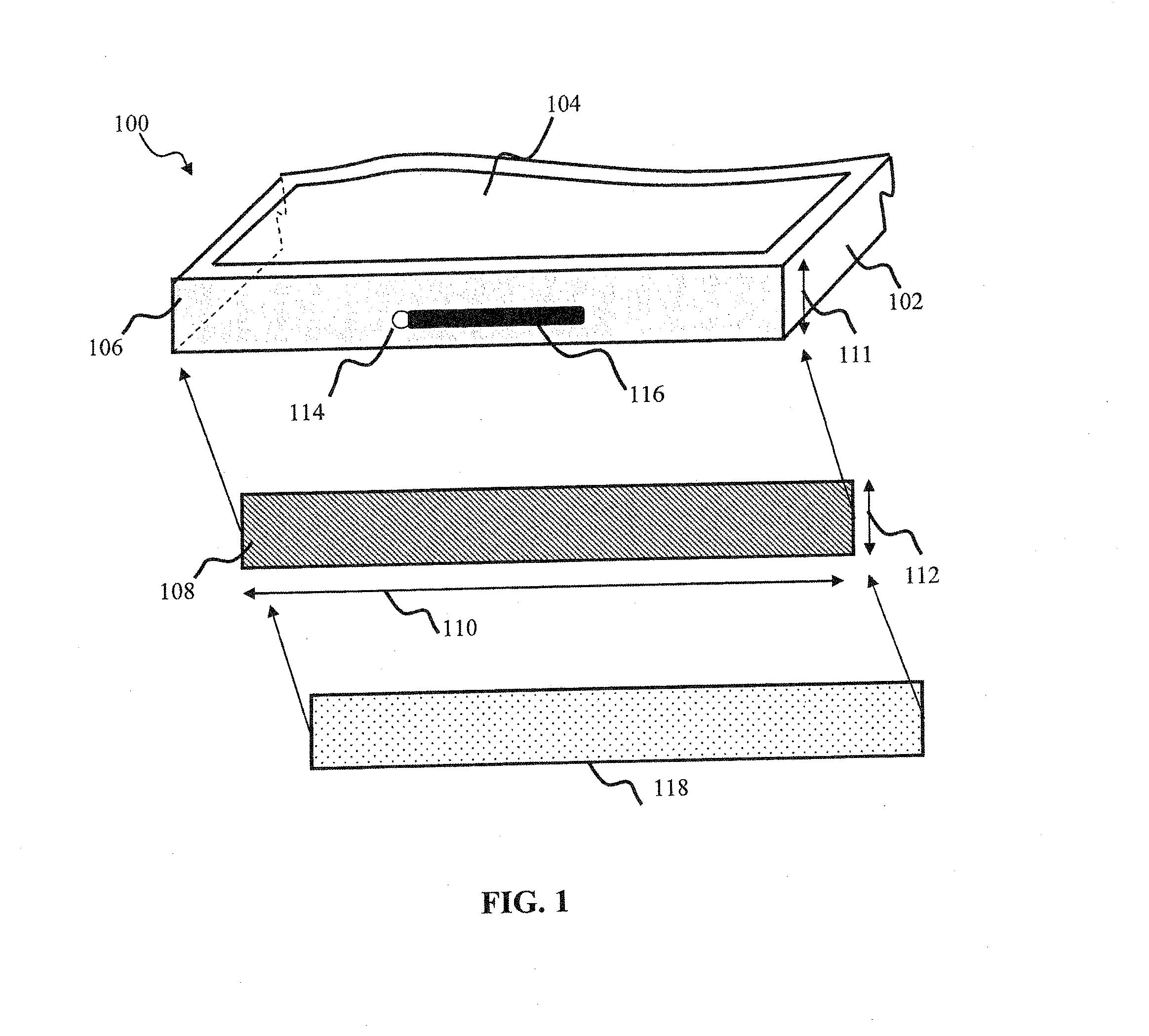
[0095]In one embodiment, a lumped reactive component 152 (e.g. inductive L or capacitive C) is coupled across the second portion 124 in order to adjust radiator electrical length. Many suitable capacitor configurations are useable in the embodiment 120, including but not limited to, a single or multiple discrete capacitors (e.g., plastic film, mica, glass, or paper), or chip capacitors. Likewise, myriad inductor configurations (e.g., air coil, straight wire conductor, or toroid core) may be used with the present disclosure.
[0096]The radiating element 108 further comprises a ground point 136 that is configured to couple the radiating element108 to the device ground (e.g., housing / chassis). In one variant, the radiating element 108 is affixed to the device via a conductive sponge at the ground coupling point 136 and to the feed cable via a solder joint at the feed point 126. In another variant, both above connections are effected via solder joints. In yet another variant, both connect...
exemplary embodiment 200
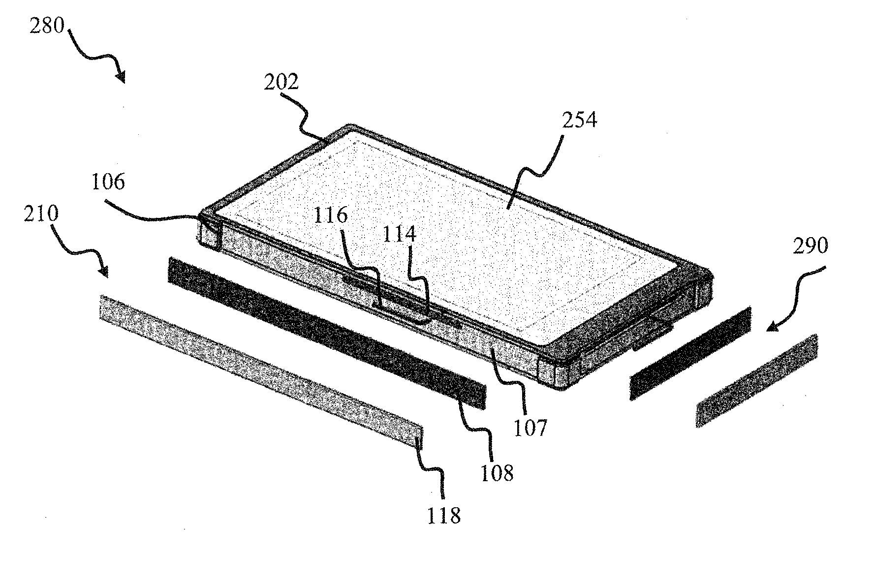
[0126]Referring now to FIG. 2A, an exemplary embodiment 200 of a mobile device comprising two antenna components configured in accordance with the principles of the present disclosure is shown and described. The mobile device comprises a metal enclosure (or chassis) 202 having a width 204, a length 212, and a thickness (height) 211. Two antenna elements 210, 230, configured similarly to the embodiment of FIG. 1A, are disposed onto two opposing sides 106, 206 of the housing 202, respectively. Each antenna element is configured to operate in a separate frequency band (e.g., one antenna 210 in a lower frequency band, and one antenna 230 in an upper frequency band, although it will be appreciated that less or more and / or different bands may be formed based on varying configurations and / or numbers of antenna elements). Other configurations may be used consistent with the present disclosure, and will be recognized by those of ordinary skill given the present disclosure. For example, both ...
PUM
 Abstract
Description
Claims
Application Information