CT device and method based on motion compensation

a technology of motion compensation and motion compensation, applied in the field of radiographic imaging, can solve the problems of difficult temporary stop of most of the other motions, affecting the accuracy of physician diagnosis of diseases, and motion artifacts in msct images

Inactive Publication Date: 2014-05-20
TSINGHUA UNIV +1
View PDF20 Cites 7 Cited by
  • Summary
  • Abstract
  • Description
  • Claims
  • Application Information

AI Technical Summary

Benefits of technology

[0010]It is an object of the present invention to provide a CT device and method based on motion compensation, which measures motion coordinates of a scanned object by using a stereo vision system and then eliminates motion artifacts in a CT image by using a motion compensation technique based on matrix transformation of an reconstructed image, thereby obtaining a CT image of high quality.
[0017]According to an embodiment of the present application, the imaging device performs a respective matrix transformation on the reconstructed image matrix based on the measured motion parameter before each back projection, so as to make the image matrix keep consistent with the pattern of the object at every moment.
[0021]The device according to the embodiments of the present invention can be embedded as a separate module into the exiting or newly developed CT devices. With the device and method according to the embodiment of the present invention, a CT image can be obtained in which motion artifacts caused by motions of the object during the CT scanning are effectively eliminated.

Problems solved by technology

For example, during medical CT scanning, due to the inherent motions of organs, there are often motion artifacts in CT images, leading to image blurring, ghosting, etc., which may affect the accuracy of physician's diagnosis of diseases.
Among the motions of these organs, except for breathing may be controlled by holding one's breath, it is difficult to temporarily stop most of the other motions.
These movements inevitably lead to motion artifacts in MSCT image, poor picture quality, and even a failed scanning.
Especially for patients, since their ability to control their bodies have been weakened, the range of movement may be more than 1 mm or even more, thereby leading to severe motion artifacts while affecting quality of CT images.
Due to a variety of restrictions such as centrifugal force, material strength and the like, this speed has already achieve the uppermost limit in industry applications, and thus it is difficult to enable a breakthrough in next few years.
Thus, it is impossible to eliminate motion artifacts by simply increasing the scanning speed.
The problems with Gating technology are that some X-ray projection data are not effectively used, leading to an increased radiation dose used in cardiac imaging.
Medical radiation has become the topmost man-made ionizing radiation, and reduction of X-ray dose in CT inspection is a major issue related to health of the public and future generations.

Method used


Image

  • CT device and method based on motion compensation
  • CT device and method based on motion compensation
  • CT device and method based on motion compensation

Examples


Embodiment Construction

[0030]Now, a detailed description will be given to the preferred embodiments of the present invention with reference to the figures, throughout which like reference signs denote identical or similar component, though illustrated in different figures. For clarity and conciseness, specific description of some known functions or structures incorporated here will be omitted otherwise the subject of the present invention may be obscured.

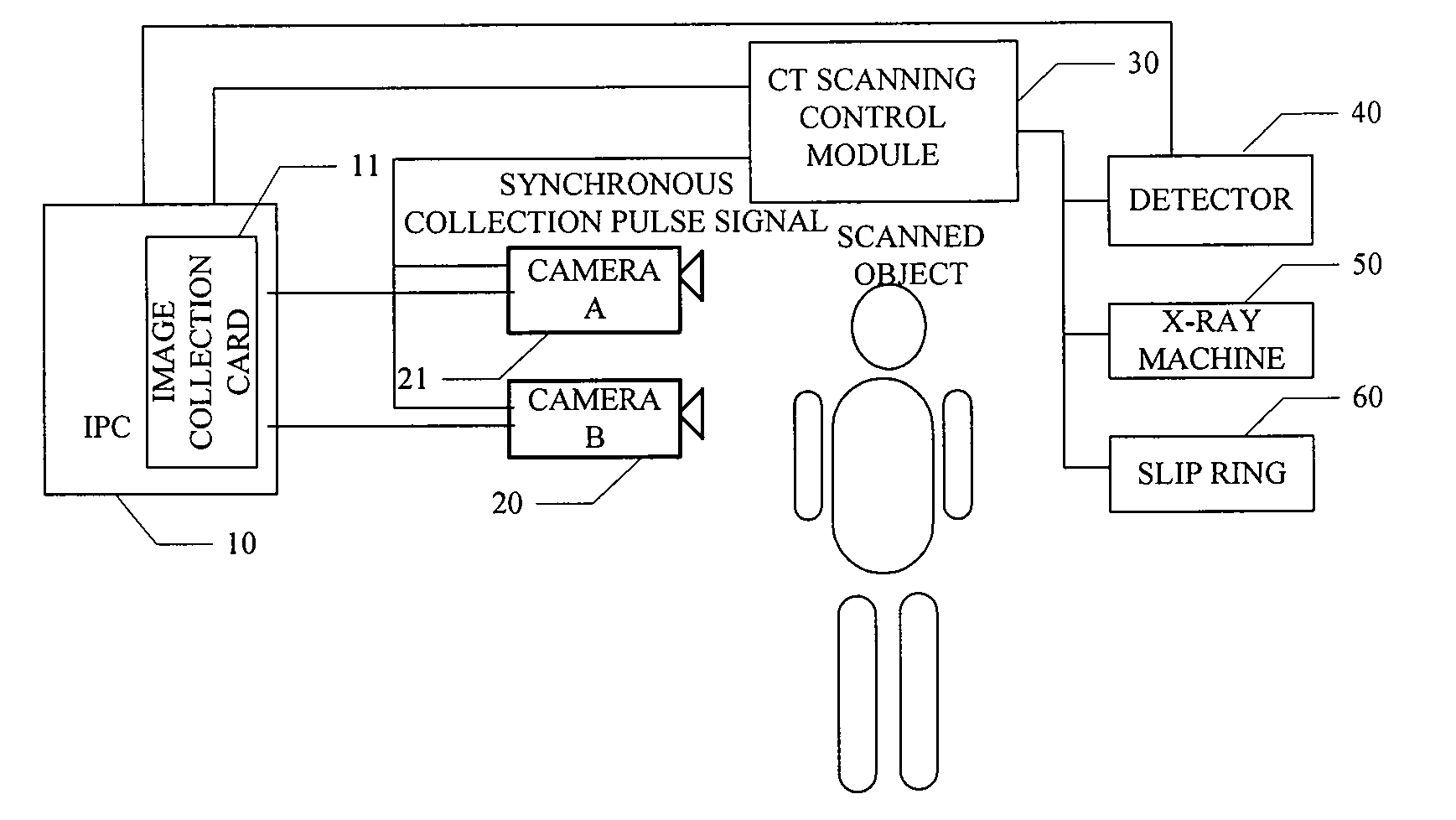
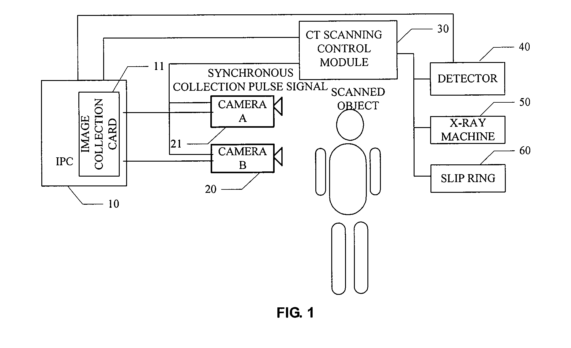
[0031]According to an embodiment of the present invention, a CT device and a method thereof based on motion compensation are proposed. FIG. 1 shows a schematic block diagram of a CT device based on motion compensation according to the embodiment of the present invention.

[0032]As show in FIG. 1, the CT device according to the present embodiment is equipped with a stereo vision system. During the CT scanning, motions of a scanned object are also collected by an image collection card 11 under the control of a CT scanning control module 30. Motion parameters ...


PUM


Abstract

A CT device and method based on motion compensation are proposed. The present invention obtains motion parameters of a target object by using a stereo-vision-based motion measurement system, and then implements motion compensation through the technology based on reconstructed image matrix transformation, thereby obtaining a clear 2D / 3D CT image while eliminating motion artifacts. The present invention can effectively eliminate motion artifacts caused by the scanned object's own motions in the CT scanning, and can be easily embedded into the existing CT scanning equipments. The present invention can improve quality of the CT images, and is especially important for CT imaging of some special groups of people that can not control their own motions, such as Parkinson's patients, infants, living mouse and so on. It can also improve ultra-high-resolution imaging of human body.

Description

CROSS-REFERENCE TO RELATED APPLICATIONS[0001]This application is a nationalization under 35 U.S.C. §371 of International Application No. PCT / CN2010 / 080312, filed on Dec. 27, 2010 and published as WO2011 / 097927, on Aug. 18, 2011, which claims priority under 35 U.S.C. §119 to Chinese Application No. 201010111359.8, filed Feb. 10, 2010, the entire contents of which are incorporated herein by reference in their entirety.FIELD OF INVENTION[0002]The present invention relates to radiography imaging, in particular to a CT (Computerized Tomography) device and method based on motion compensation.BACKGROUND OF THE INVENTION[0003]Since 1972, Hounsfield invented the first CT machine, CT technology has brought a revolutionary impact to medical diagnosis and nondestructive testing in industry and CT has become one important means of detection in the medical, biotechnology, aerospace and defense sectors and the like industries. As technology advances, scan modes and imaging methods for CT are conti...

Claims


Application Information

Patent Timeline
Patent Type & Authority Patents(United States)
IPC IPC(8): G06K9/00G03B42/02
CPCA61B6/5264G06T11/005A61B6/032G06T7/2086G06T2207/10081G06T2211/412G06T7/285
Inventor LI, LIANGCHEN, ZHIQIANGZHANG, LIKANG, KEJUNLI, YUANJINGZHAO, ZIRANLIU, YINONGXING, YUXIANGJIN, XIN
Owner TSINGHUA UNIV
Why Eureka
Try Eureka