Power driven duster and cleaner apparatus

a technology of power-driven duster and cleaner, which is applied in the direction of carpet cleaner, photosensitive materials, instruments, etc., can solve the problems of time-consuming process, unsatisfactory results, and dusting or cleaning problems, and achieve the effect of quick removal of dus

Active Publication Date: 2014-06-17
CROWN DOWN CLEANERS
View PDF19 Cites 7 Cited by
  • Summary
  • Abstract
  • Description
  • Claims
  • Application Information

AI Technical Summary

Benefits of technology

[0007]Therefore, one object of this invention is to provide a hand held device that can satisfactorily and quickly remove dust from molding, wainscoting and similar ledges, as well as from crevices, corners and other non-flat surfaces such as three-dimensional decorative forms on furniture and similar articles.
[0008]Another object of this invention is to provide a hand held device that can dust or clean surfaces, such as crown molding or top surfaces of tall furniture, that are above the normal reach of a person.
[0009]Still another object of this invention is to provide a hand held device that can safely clean the top edges of paintings, taperistries and other hung objects without knocking them to the floor.

Problems solved by technology

The cleaning of homes, commercial office building or other similar structures has provided the cleaning industry with many challenging dusting or cleaning issues.
One such issue is removing the dust from narrow ledges, such as floor molding, wainscoting and other similar structures so that it can be vacuumed and removed from the building.
Other such difficult dusting structures would include various crevices and corner areas common in these structures.
This is a very time consuming process that in many cases achieves unsatisfactory results.
Another time consuming situation occurs when dusting table or desk surfaces having various small objects positioned on the surfaces.
Safety and other issues arise when trying to dust areas that are above the reach of the cleaning person that requires the person to climb a ladder to reach the areas, or near the floor that requires the cleaning person to stoop or get on their knees to reach the areas.
In addition to the safety issues, the dusting process is very time consuming.

Method used


Image

  • Power driven duster and cleaner apparatus
  • Power driven duster and cleaner apparatus
  • Power driven duster and cleaner apparatus

Examples


Embodiment Construction

[0024]Without any intent to limit the scope of this invention, reference is made to the figures in describing the preferred embodiments of the invention.

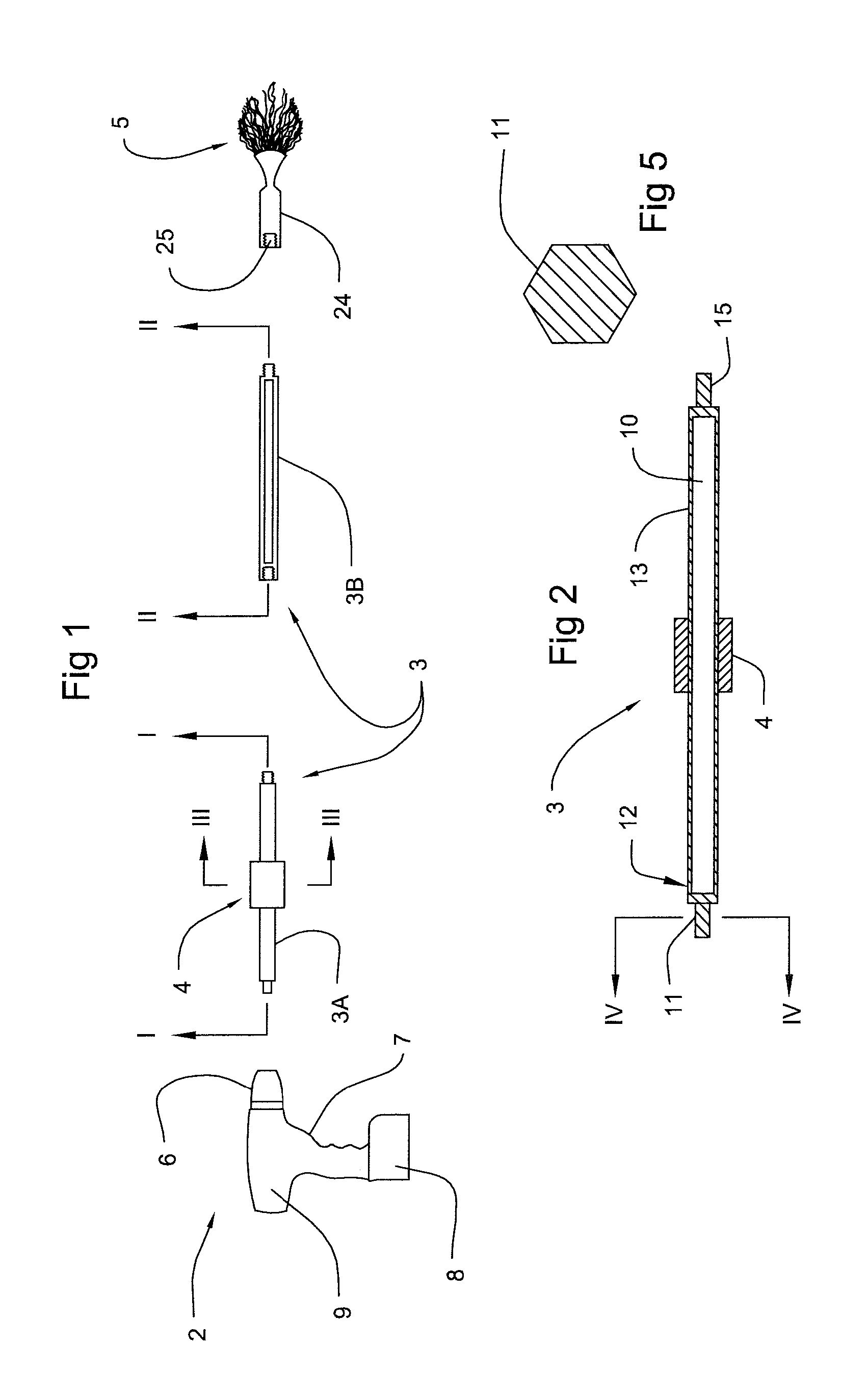
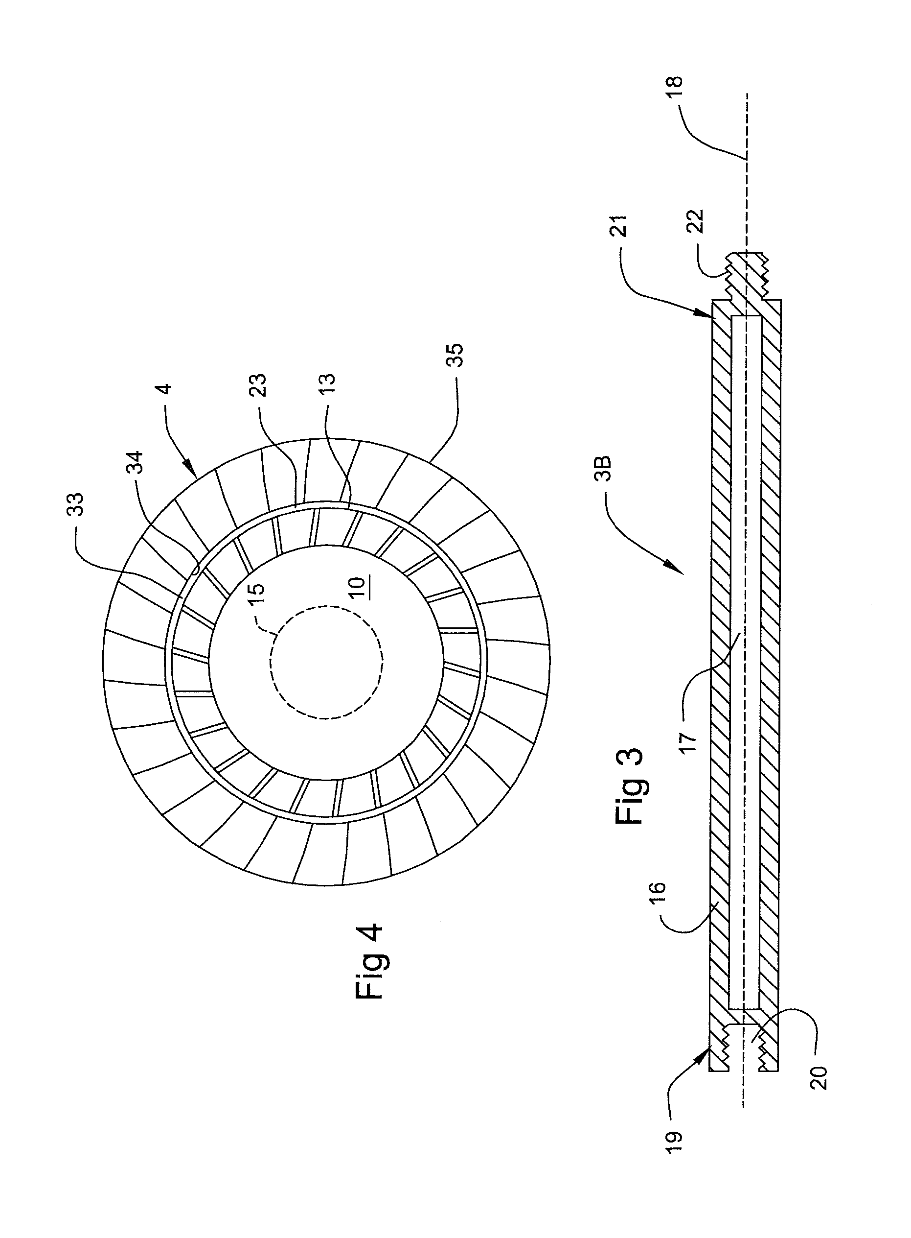
[0025]Referring now to the figures, the preferred embodiment of hand held apparatus 1 includes a conventional electric drill 2, at least one elongated, tubular extension member 3, a tubular hand guide member 4 constructed to glidingly fit along the extension member 3, and a dusting member 5.

[0026]Drill 2 has a chuck 6 that rotates when the drill 2 is activated by switch 7 that controls the battery 8 to electrically connect to the drill motor 9. It is preferred that drill 2 be cordless to eliminate extension cords that would have to be plugged into a wall socket. It is also preferred that drill 2 be a variable speed drill having multiple torque settings to provide better control over the rotational speed and the torque that is delivered to the dusting member 5.

[0027]The number of elongated extension members 3 that are utilized depend...


PUM


Abstract

A hand held dusting apparatus for use with a motor provided with a rotating axle, such as a variable speed drill, includes an elongated extension member attachable at one end to the rotating axle and a dusting member having a body section attachable to the opposite end of the elongated extension member and a dusting section constructed having multiple strands of synthetic fiber materials extending from the body section. In a preferred embodiment the apparatus further includes a tubular hand guide member fitted about the extension member and constructed to slide along the extension member. In another preferred embodiment the body of dusting section has a mid-section that can be pivoted to allow the dusting elements to rotate about an axis set at an angle to the axis of the extension member.

Description

BACKGROUND OF THE INVENTION[0001]1. Field of the Invention[0002]This invention relates in general to apparatus for dusting or cleaning, and more particular to power driven apparatus for dusting or cleaning.[0003]2. Prior Art[0004]The cleaning of homes, commercial office building or other similar structures has provided the cleaning industry with many challenging dusting or cleaning issues. One such issue is removing the dust from narrow ledges, such as floor molding, wainscoting and other similar structures so that it can be vacuumed and removed from the building. Other such difficult dusting structures would include various crevices and corner areas common in these structures. Also three-dimensional decorative areas in furniture contained in these structures or on the edge of paintings, taperistries or other wall mounted art objects are further examples of problem areas. Currently, it is necessary to use rags or other cloth materials to hand rub the dust catching areas. This is a v...

Claims


Application Information

Patent Timeline
Patent Type & Authority Patents(United States)
IPC IPC(8): A46B13/02A46B17/02
CPCA47L13/38
Inventor MANNING, PAUL, D.
Owner CROWN DOWN CLEANERS
Why Eureka
Try Eureka