Transformerless charger with terminal safety features

a transformerless charger and safety feature technology, applied in the direction of safety/protection circuits, electrochemical generators, transportation and packaging, etc., can solve the problems of increased cost and weight, inconvenience of a charger designed to have limited usability, and difficult so as to achieve convenient safe cleaning of the charging terminal. , the effect of ensuring safety

Inactive Publication Date: 2006-04-04
UNIDEN
View PDF3 Cites 5 Cited by
  • Summary
  • Abstract
  • Description
  • Claims
  • Application Information

AI Technical Summary

Benefits of technology

[0007]Accordingly, it is an object of the present invention to provide a transformerless charger for preventing a human body from receiving an electric shock from a charging terminal and for making it easy to clean the charging terminal.
[0009]Since this configuration enables the control to allow or block the passage of a current to the charging terminal in response to the open or closed state of the flip cover, it is possible to secure safety by preventing a human body from receiving an electric shock via a charging terminal, and to easily clean the charging terminal.
[0010]The switch allows the passage of a current between the charging terminal and the transformerless power supply circuit when the flip cover is closed, and the switch blocks the passage of a current between the charging terminal and the transformerless power supply circuit when the flip cover is opened. Accordingly, when the flip cover is opened, the charging terminal is not energized, and therefore, it is possible to clean the charging terminal safely. When the flip cover is closed, the charging terminal is covered with the flip cover, and therefore, it is possible to prevent a human body from receiving an electric shock.
[0011]Preferably, this flip cover is attached to a charger body via a hinge mechanism. Accordingly, it is possible to prevent the flip cover going missing.
[0013]Since the passage or blocking of a current to the charging terminal is controlled in response to an attached or detached state of the charging terminal cover, it is possible to secure safety by preventing a human body from receiving an electric shock via the charging terminal and to easily clean the charging terminal.
[0014]This switch allows the passage of a current between the charging terminal and the transformerless power supply when the charging terminal cover is attached to the charger body, and the switch blocks the passage of a current between the charging terminal and the transformerless power supply when the charging terminal cover is detached from the charger body. Accordingly, when the charging terminal cover is detached, the charging terminal is not energized, and therefore, it is possible to clean the charging terminal safely. When the charging terminal cover is attached, the charging terminal is covered with the charging terminal cover, and therefore, it is possible to prevent a human body from receiving an electric shock.

Problems solved by technology

If this kind of charger is provided with a transformer power supply circuit that prevents a human body from receiving an electric shock from the charging terminal, this may cause an increase in cost and weight.
Moreover, since the transformer which requires a relatively large volume has to be incorporated into the charger, such construction causes the inconvenience of a charger which is designed to have limited usability.
However, if an area around the charging terminal is covered with some protective covering member, it is effective for the prevention of electric shocks, but it makes it difficult to clean the charging terminal.
Particularly, in an environment containing a lot of dust or moisture, exogenous materials which make contact with the charging terminal cause chemical reactions, thereby bringing about a problem of shortening the life of the charging terminal.

Method used


Image

  • Transformerless charger with terminal safety features
  • Transformerless charger with terminal safety features
  • Transformerless charger with terminal safety features

Examples


embodiment 1

[Embodiment 1]

[0021]Embodiment 1 of the present invention is explained below with reference to each of the attached drawings.

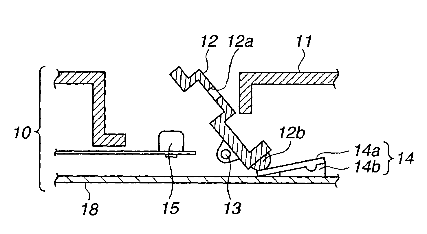
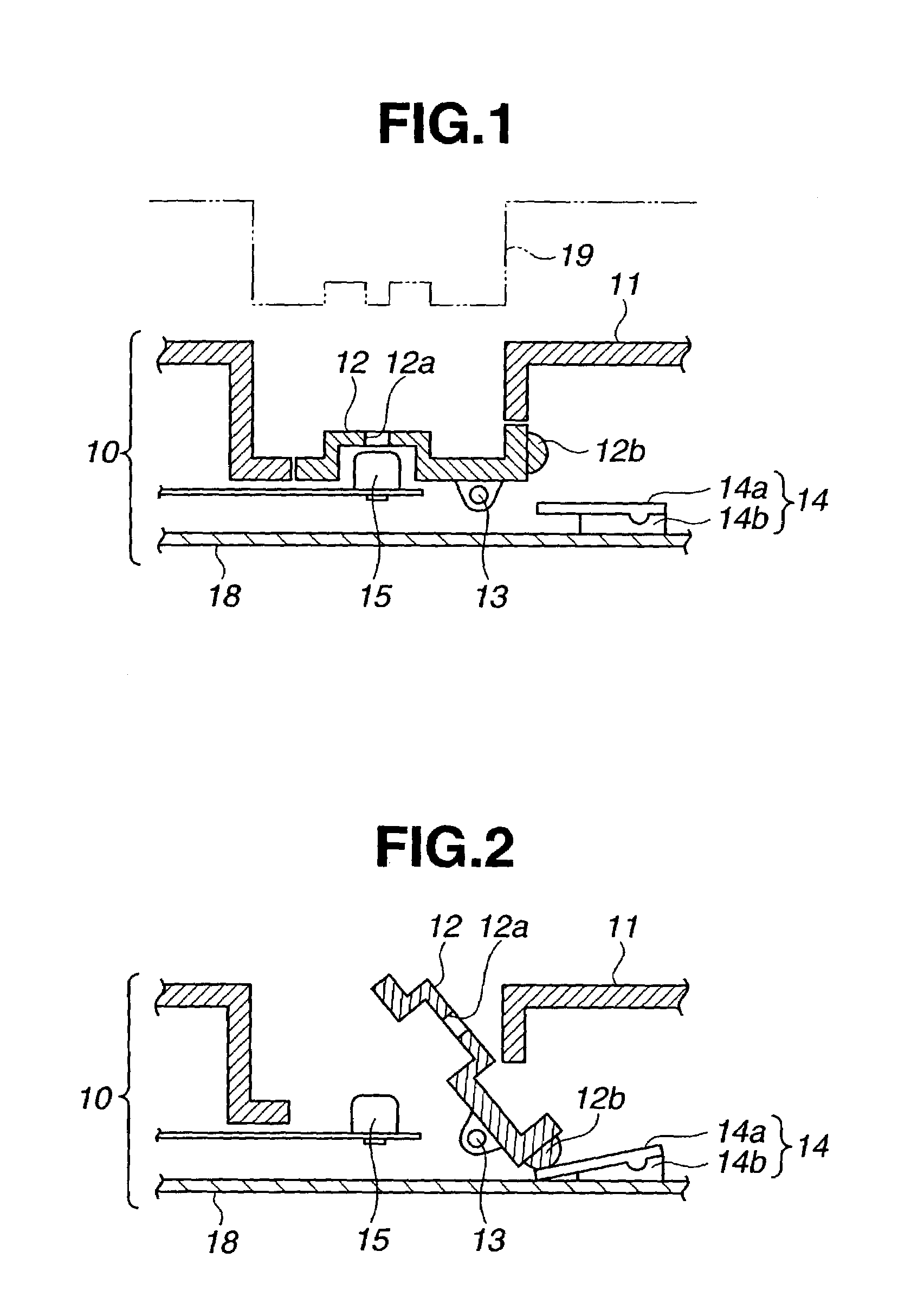
[0022]FIG. 1 is a block diagram of a transformerless charger 10 according to Embodiment 1, which shows its cover flipping mechanism shown as the main part in the drawing. Referring to FIG. 1, a reference numeral 15 is a charging terminal for charging a secondary battery placed in the rechargeable electronic equipment 19, a reference numeral 12 is a flip cover for covering the charging terminal 15 to prevent the charging terminal 15 from being exposed at the surface of the charger, and a reference numeral 14 is a switch that allows or blocks the passage for a current between the charging terminal 15 and a transformerless power supply circuit 16 (see FIG. 3) in synchronization with an opening or closing motion of the flip cover 12.

[0023]A charger body 11 and the flip cover 12 constitute a mounting table for mounting the rechargeable electronic equipment 19. The ...

embodiment 2

[Embodiment 2]

[0030]Preferred Embodiment 2 of the present invention is explained below with reference to FIG. 4.

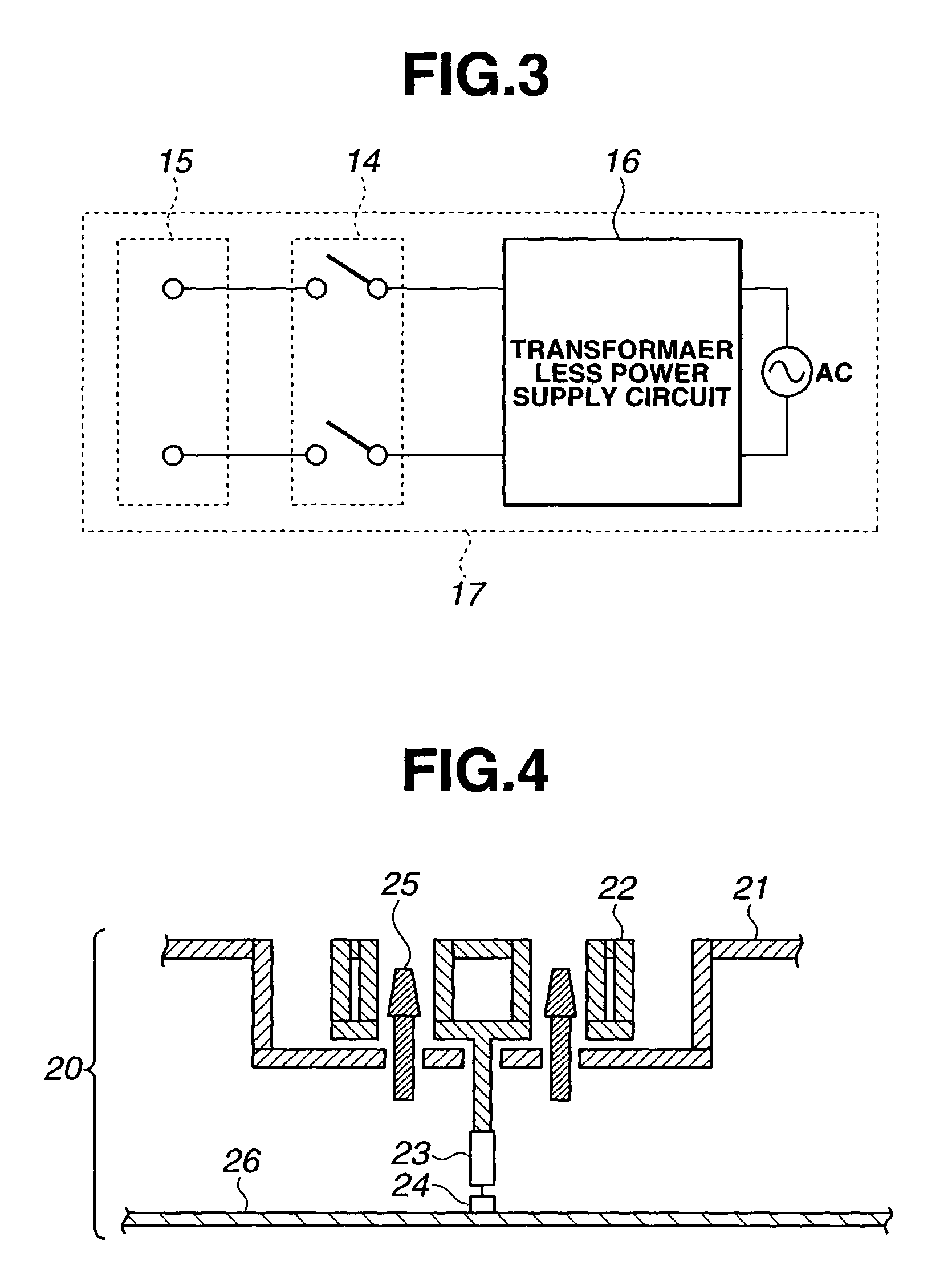
[0031]FIG. 4 is a block diagram of a transformerless charger 20, which shows an attaching and detaching mechanism of a charging terminal cover 22 as the main part in the drawing. In FIG. 4, a reference numeral 21 is a charger body, a reference numeral 25 is a charging terminal for charging rechargeable electronic equipment, and a reference numeral 22 is a charging terminal cover for covering an area around the charging terminal 25 to prevent the charging terminal 25 from being exposed. The charging terminal cover 22 is attachable to and detachable from the charger body 21. As shown in FIG. 4, when the charging terminal cover 22 is attached to the charger body 21, charging voltage is supplied to the charging terminal 25 from the transformerless power supply circuit, and the transformerless charger 20 is in a state capable of charging the rechargeable electronic equipment. M...

embodiment 3

[Embodiment 3]

[0034]Preferred Embodiment 3 of the present invention is explained below with reference to FIG. 5.

[0035]FIG. 5 is a block diagram of a transformerless charger 30, which shows an attaching and detaching mechanism of a charging terminal cover 32 as the main part in the drawing. In FIG. 5, a reference number 31 is a charger body, a reference number 35 is a charging terminal for charging the rechargeable electronic equipment, and a reference number 32 is the charging terminal cover for covering an area around the charging terminal 35 to prevent the charging terminal 35 from being exposed. The charging terminal cover 32 is attachable to and detachable from the charger body 31. When the charging terminal cover 32 is attached to the charger body 31, the charging terminal 35 is energized, and the rechargeable electronic equipment is charged via a port 32a that is situated in the charging terminal cover 32. On the other hand, when the charging terminal cover 32 is detached from...


PUM

PropertyMeasurementUnit
charging voltageaaaaaaaaaa
currentaaaaaaaaaa
weightaaaaaaaaaa

Abstract

It is an object of the present invention to provide a transformerless charger capable of preventing a human body from receiving an electric shock from a charging terminal, and of making it easy to clean the charging terminal. In order to achieve this object, the transformerless charger of the present invention comprises: a charging terminal for supplying charging voltage to rechargeable electronic equipment; a transformerless power supply circuit for supplying charging voltage to the charging terminal; a flip cover that covers the charging terminal to prevent the charging terminal from being exposed; and a switch that allows or blocks the passage of a current between the charging terminal and the transformerless power supply circuit in synchronization with an opening or closing motion of the flip cover. This configuration makes it possible to control the passage or blocking of a current at the charging terminal in response to the open or closed state of the flip cover, and therefore, it is possible to secure safety to prevent a human body from receiving an electric shock via the charging terminal and it is also possible to easily clean the charging terminal.

Description

BACKGROUND[0001]1. Field of the Invention[0002]The present invention relates to a transformerless charger for charging a secondary battery placed in rechargeable electronic equipment such as a cordless phone or a mobile phone.[0003]2. Description of the Related Art[0004]Conventional chargers for charging secondary batteries placed within various kinds of electronic equipment for home appliances, such as cordless phones are constructed in order to facilitate charging operations, in such a manner that the relevant rechargeable electronic equipment can be charged simply by mounting the rechargeable electronic equipment on a mounting table on which a charging terminal is provided. If this kind of charger is provided with a transformer power supply circuit that prevents a human body from receiving an electric shock from the charging terminal, this may cause an increase in cost and weight. Moreover, since the transformer which requires a relatively large volume has to be incorporated into...

Claims


Application Information

Patent Timeline
Patent Type & Authority Patents(United States)
IPC IPC(8): H01M10/46H02J7/00
CPCH02J7/0042H02J7/0029
Inventor MAEBASHI, HIROSHINAGAI, KENJIYAMAMOTO, SATORU
Owner UNIDEN
Why Eureka
Try Eureka