Absorber for a thermal solar panel

a solar panel and absorption technology, applied in solar heat collectors, solar heat devices, solar heat devices, etc., can solve the problems of mechanical complexity and fragility of the absorption device, and less efficient path of heat-bearing fluid, so as to achieve optimal heat yield and reliably support the pressure of heat-bearing fluid

Active Publication Date: 2014-06-24
LALIVE FRANCOIS +1
View PDF9 Cites 3 Cited by
  • Summary
  • Abstract
  • Description
  • Claims
  • Application Information

AI Technical Summary

Benefits of technology

[0010]The aim of the present invention is to respond to the above-mentioned drawbacks, at the same time retaining advantages associated with the second category, by providing an efficacious absorber, that is, having optimised heat yield, but also simple, robust and tight, that is, able to reliably support the pressure of heat-bearing fluid which it contains.
[0012]In this way, it is possible to keep joined together the two plates by using a limited number of connection points without diminishing the communication surfaces between the protuberances of the two plates and without risk for tightness of the absorber to the extent where the cavities ensure sufficient space to make an efficacious connection point. The resulting absorber is remarkable in that it combines obtaining good heat yield with a fixing system via non-traversing connection ensuring excellent hold and perfect tightness between the plates.
[0013]According to an advantageous variant embodiment, the hollow geometric shapes have a general annular protruding form. Such a form has the advantage of being simple and therefore easily swageable while ensuring an optimised communication surface between the annular forms of a plate with the offset forms of the other plate. Also, it has been shown within the scope of the present invention that the path of the resulting heat-bearing fluid both maximises the sinuous character of the path travelled by the heat-bearing liquid, ensuring optimised heat yield, and also avoiding losses of heat-bearing fluid via the absorber on the possible angles of the geometric shapes of the matrix able to cause unwanted excessive dilation for reasons of mechanical resistance of the absorber.
[0014]According to another advantageous variant embodiment, the non-traversing connection points located in cavities are made by mechanical deformation of the two plates so as to join them together. The non-traversing connection points preferably located in cavities are points for clinching the two plates together. It is evident in this respect that the clinching is a mechanical assembly technique of plates, whereof the principle consists of connecting the two plates by stamping between a punch and a matrix without extra material. Even though such a solution requires a considerable space around the clinching point, it proves particularly robust while being rapid, and perfectly adequate due to the cavities in which these connection points are made. Alternatively, the non-traversing connection points located in cavities are rivets swaging the two plates together without perforating any of them.
[0015]According to another advantageous variant embodiment, a continuous connection at the periphery of the plates is obtained by ultrasonic welding or laser fusion or welding of the two plates together. The major advantage of using welding by ultrasound or laser fusion or welding is fixing the two plates tightly together, without leaving shavings from plates or other waste material between the plates. Also, this type of continuous welding proves to be faster than traditional welding techniques, this advantage being amplified by the continuous character of the welding. Advantageously, at least one ultrasonic welding or laser fusion or welding line of the two plates is added between the geometric shapes. Adding such welding lines while retaining the advantages of this type of welding without waste reinforces holding the plates together.
[0016]According to another advantageous variant embodiment, the inlet means and outlet means of the heat-bearing fluid are arranged diagonally opposite on the external face of one of the two plates. These inlet and outlet means ensure circulation through the absorber and are localised on the external face of the lower plate, once mounted in a panel, such that the joints used are protected from direct exposure to light radiation, which could alter their tightness while retaining maximal surface exposure on the external face of the upper plate of the absorber as well as protection of the glass plate of the panel intended to cover the absorber. Advantageously, these inlet means and outlet means are end fittings arranged on a flat portion of the lower plate opposite to a geometric form of the upper plate to reduce the total thickness of the absorber.

Problems solved by technology

Such thermal solar panels have a number of drawbacks, including more especially the mechanical complexity and fragility of the absorber as well as a relatively low yield due to the low volume of heat-bearing fluid for a determined glazed surface of the solar panel.
Even though the solar sensor presented within the scope of document CH 624 753 has a higher yield and is mechanically simpler than those comprising tubes, it still has some drawbacks, in particular resistance to pressure exerted by heat-bearing fluid on the metal plates of the sensor.
In fact, if the space between the bosses is increased, all the more reducing the communication surfaces between the bosses of the two plates and resulting in making the path of the heat-bearing fluid less efficient, then this space is kept as such and in this case the risk of perforation of a boss is considerably higher and the tightness of the sensor is threatened.

Method used


Image

  • Absorber for a thermal solar panel
  • Absorber for a thermal solar panel
  • Absorber for a thermal solar panel

Examples


Embodiment Construction

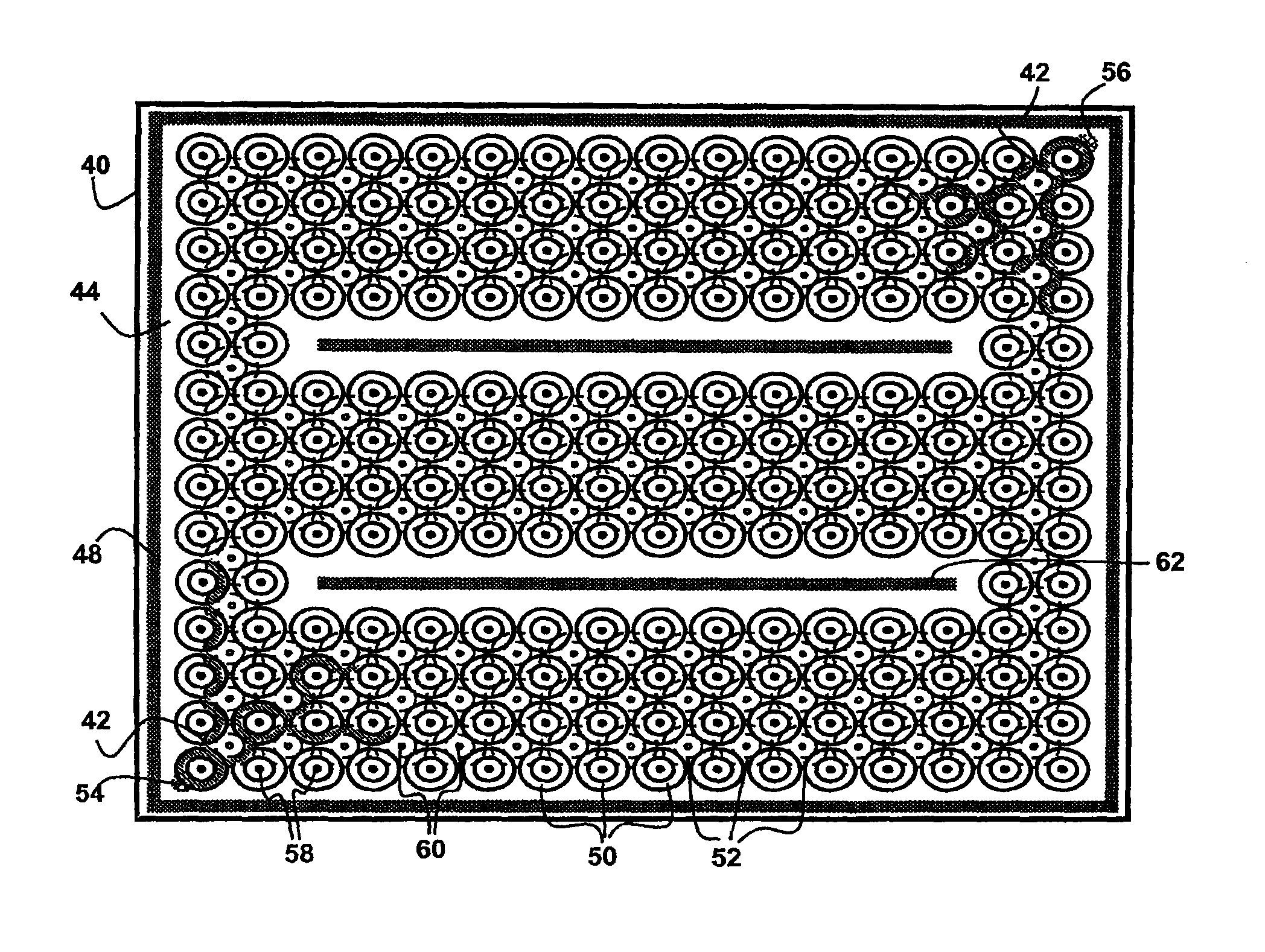
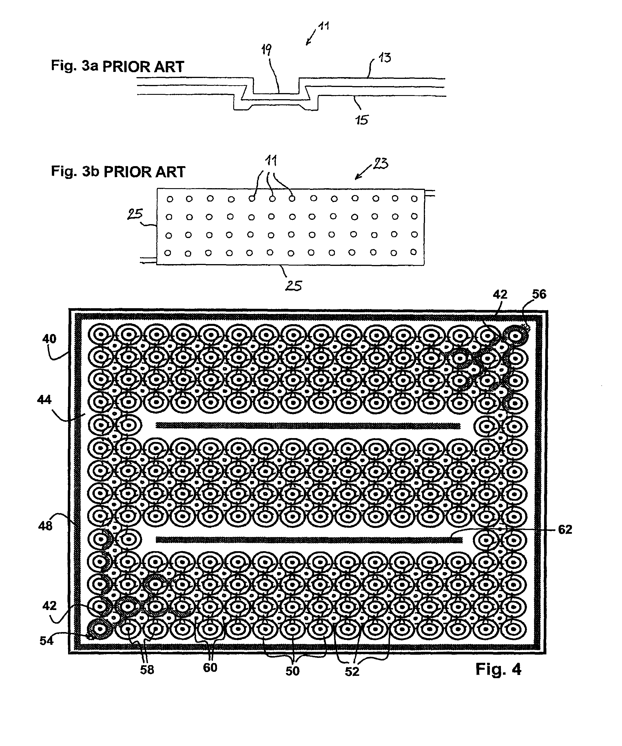
[0028]The invention will be described hereinbelow solely by way of example in relation to FIGS. 4 to 8. Reference is made initially to the FIG. 4 which illustrates a plan view of an absorber for a solar panel according to a preferred embodiment of the present invention. The absorber 40 for solar panel is provided to contain heat-bearing fluid 42. The absorber is mainly made by means of two metal plates superposed and fixed together tightly. In this figure, only the upper plate 44 is visible, the lower plate (46, FIG. 6a) being located underneath.

[0029]A continuous connection 48 obtained by ultrasonic welding or laser fusion continue of the two plates ensemble is advantageously provided for tight fixing on the periphery of the plates. This first solution proves the simplest and the fastest to carry out, at the same time ensuring proper peripheral tightness. An alternative solution, though less interesting due to being more complex to execute, consists of folding the edges of one of t...


PUM


Abstract

The invention relates to an absorber (40) for a solar panel, provided for containing a heat transfer fluid (42), including first (44) and second (46) plates arranged opposite each other and attached to each other via a plurality of connection points (58, 60), first and second matrices having protruding geometrical shapes (50, 52) formed on the outer surfaces of the first and second plates, respectively, the matrices being offset relative to each other so as to provide a flow path for the heat transfer fluid in the absorber, an inlet (54) and an outlet (56) for the heat transfer fluid arranged at both ends of the heat transfer fluid flow path, respectively, characterized in that at least some of the geometrical shapes have a generally protruding shape with a recess at the center thereof so as to form a cavity (64, 66), and in that at least some of said non-through connection points are provided in at least some of said recesses.

Description

REFERENCE TO RELATED APPLICATIONS[0001]This application is the U.S. nationalization of PCT / EP2009 / 050119, filed 7 Jan. 2009, which is hereby incorporated by reference. This application claims priority from Patent Application No. EP 08106014.7, filed 18 Dec. 2008, which is hereby incorporated by reference.TECHNICAL FIELD[0002]The present invention relates in general to a thermal solar panel consisting of converting light into heat. More particularly, the present invention relates to an absorber for such a solar panel provided to contain liquid or heat-bearing fluid.TECHNOLOGICAL BACKGROUND[0003]The prior art discloses numerous types of thermal solar panels comprising an absorber containing heat-bearing fluid which may be water for example, water mixed with an antigel or even just air.[0004]According to a first category of thermal solar panels illustrated in FIG. 1, these panels 1 comprise an absorber 2 formed by tubes 3 fitted with fins in which heat-bearing fluid circulates in close...

Claims


Application Information

Patent Timeline
Patent Type & Authority Patents(United States)
IPC IPC(8): F24J2/22F24S10/55F24S10/50
CPCF24J2/205F24J2/22Y02E10/44F24S10/504F24S10/55
Inventor LALIVE, FRANCOISLALIVE, LUDMILLA
Owner LALIVE FRANCOIS
Why Eureka
Try Eureka