Conveyor controllers

a conveyor system and controller technology, applied in the field of conveyor controllers, can solve the problems of inability to discern additional information, inability to advance control the feedback capability of conventional controllers, and inability to track different sized articles

Active Publication Date: 2014-06-24
INSIGHT AUTOMATION INC
View PDF75 Cites 65 Cited by
  • Summary
  • Abstract
  • Description
  • Claims
  • Application Information

AI Technical Summary

Problems solved by technology

However, conventional controllers for conveyor systems often lack the capability for advanced control of feedback.
For example, conventional controllers are able to determine whether an article is sensed by a photo-eye but unable to discern any additional information about that article.
Moreover, conventional controllers are often unable to track differently sized articles as they move through various portions of the conveyor.
This, in turn, can result in a jam situation or result in collisions between articles.
Moreover, conventional controllers are often difficult to maintain and replace.
But this conventional programming is time consuming and laborious, often involving dip-switch setting and complex algorithmic management to implement even a simple run of a conveyor (e.g., a “linear” conveyor without any diverts or mergers).
Moreover, in the event that all conventional controllers need not be reprogrammed simply to replace one, conventional replacement of a controller often involves programming that replacement controller ahead of time.
This can be a laborious process, as the exact configuration of a previous controller may not be available, requiring the configuration to be recreated from scratch.

Method used


Image

  • Conveyor controllers
  • Conveyor controllers
  • Conveyor controllers

Examples


Embodiment Construction

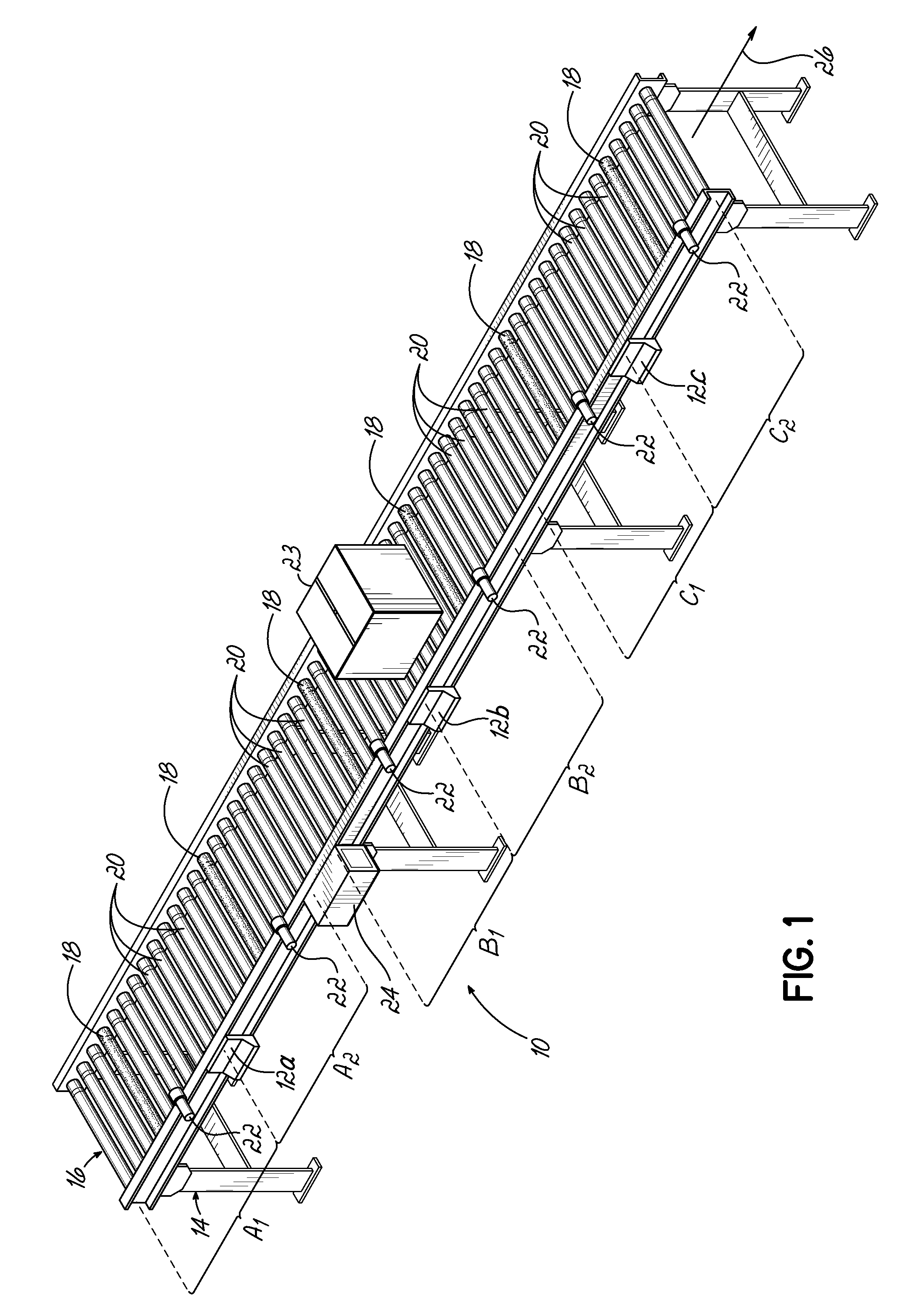
[0044]FIG. 1 is a perspective illustration of a portion of a conveyor system 10 that uses one or more modular conveyor controllers 12a-c consistent with embodiments of the invention. In particular, the illustrated portion of the conveyor system 10 includes a conveyor assembly 14 which in turn includes a conveyor belt 16 that has motorized rollers 18 interspersed with non-motorized rollers 20. The conveyor assembly 14 further includes a plurality of sensors 22 and a power supply unit 24. The sensors 22 are configured to detect the presence or absence of an article 23 conveyed on the conveyor assembly 14, while the power supply unit 24 is configured to provide power to one or more modular conveyor controllers 12, the motorized rollers 18, and / or the sensors 22.

[0045]As illustrated in FIG. 1, each modular conveyor controller 12 (referred to hereinafter as “controller”12) interfaces with and / or controls up to two motorized rollers 18 and up to two sensors 22. As such, each controller12 ...


PUM


Abstract

Various methods, apparatuses, and program products that are used to control at least a portion of a conveyor, determine information about an article conveyed by the conveyor, or otherwise operate a conveyor are provided. One method includes detecting whether a second conveyor controller is connected to the first conveyor controller and, in response to detecting that there is a second conveyor controller connected to the first conveyor controller, identifying whether the second conveyor controller is connected to a predetermined network interface of the first conveyor controller. The method further includes configuring the first conveyor controller to rotate a motorized roller in a first predetermined direction if a second conveyor controller is connected to the predetermined network interface and configuring the first conveyor controller to rotate the motorized roller in a second predetermined direction if a second conveyor controller is not connected to the predetermined network interface.

Description

FIELD OF THE INVENTION[0001]The present invention relates controlling conveyor systems with networked conveyor controllersBACKGROUND OF THE INVENTION[0002]Conveyors are used in a number of applications to convey an article from a first point to a second point. As an example, conventional conveyors can include roller conveyors, which include a plurality of motorized and non-motorized rollers, as well as belt conveyors, which include belts that are driven by one or more motorized rollers. Typically, one or more sections of the conventional conveyor are controlled by a controller, such as a computer. The controller generally controls the motorized rollers or motors that operate the belt of the conveyor to move an article along the conveyor. In conventional conveyor controllers, the controller also attempts to keep track of whether an article is being conveyed by monitoring sensors, such as photo-eyes, configured on the conveyor.[0003]However, conventional controllers for conveyor syste...

Claims


Application Information

Patent Timeline
Patent Type & Authority Patents(United States)
IPC IPC(8): B65G13/06
CPCB65G43/10B65G43/00G05B19/4189G05B2219/25081B65G47/261Y02P90/02B65G13/02B65G23/08
Inventor COMBS, CHARLES R.KNAPKE, JAMES P.PETROV, DIMITAR I.BARNES, TIMOTHY A.SELLERS, DAVID W.
Owner INSIGHT AUTOMATION INC
Why Eureka
Try Eureka