Centrifugally decoupling touchdown bearings

a technology of centrifugally decoupling and bearings, which is applied in the direction of sliding contact bearings, magnetic bearings, mechanical bearings, etc., can solve the problems of well known friction and wear problems, mechanical bearings, air bearings, and poorly adapted for vacuum use, etc., and achieve the effect of reducing friction and wear, and improving the service li

Active Publication Date: 2014-06-24
LAWRENCE LIVERMORE NAT SECURITY LLC
View PDF13 Cites 14 Cited by
  • Summary
  • Abstract
  • Description
  • Claims
  • Application Information

AI Technical Summary

Problems solved by technology

Such bearings necessarily involve mechanical contact between the rotating element and the bearing components, leading to problems of friction and wear that are well known.
Even non-contacting bearings, such as air bearings, involve frictional losses that can be appreciable, and are sensitive to the presence of dust particles.
In addition, mechanical bearings, and especially air bearings, are poorly adapted for use in a vacuum environment.
All presently available commercial magnetic bearing / suspension elements are subject to limitations, arising from a fundamental physics issue, that increase their cost and complexity.
These limitations make the conventional magnetic bearing elements unsuitable for a wide variety of uses where complexity-related issues, the issue of power requirements, and the requirement for high reliability are paramount.
In other words if such a bearing element is designed to be stable against radially directed displacements, it will be unstable against axially directed displacements, and vice versa.
Needless to say, magnetic bearings that employ superconductors are subject to the limitations imposed by the need to maintain the superconductor at cryogenic temperatures, as well as limitations on the magnitude of the forces that they can exert, as determined by the characteristics of the superconductor employed to provide that force.

Method used


Image

  • Centrifugally decoupling touchdown bearings
  • Centrifugally decoupling touchdown bearings
  • Centrifugally decoupling touchdown bearings

Examples


Embodiment Construction

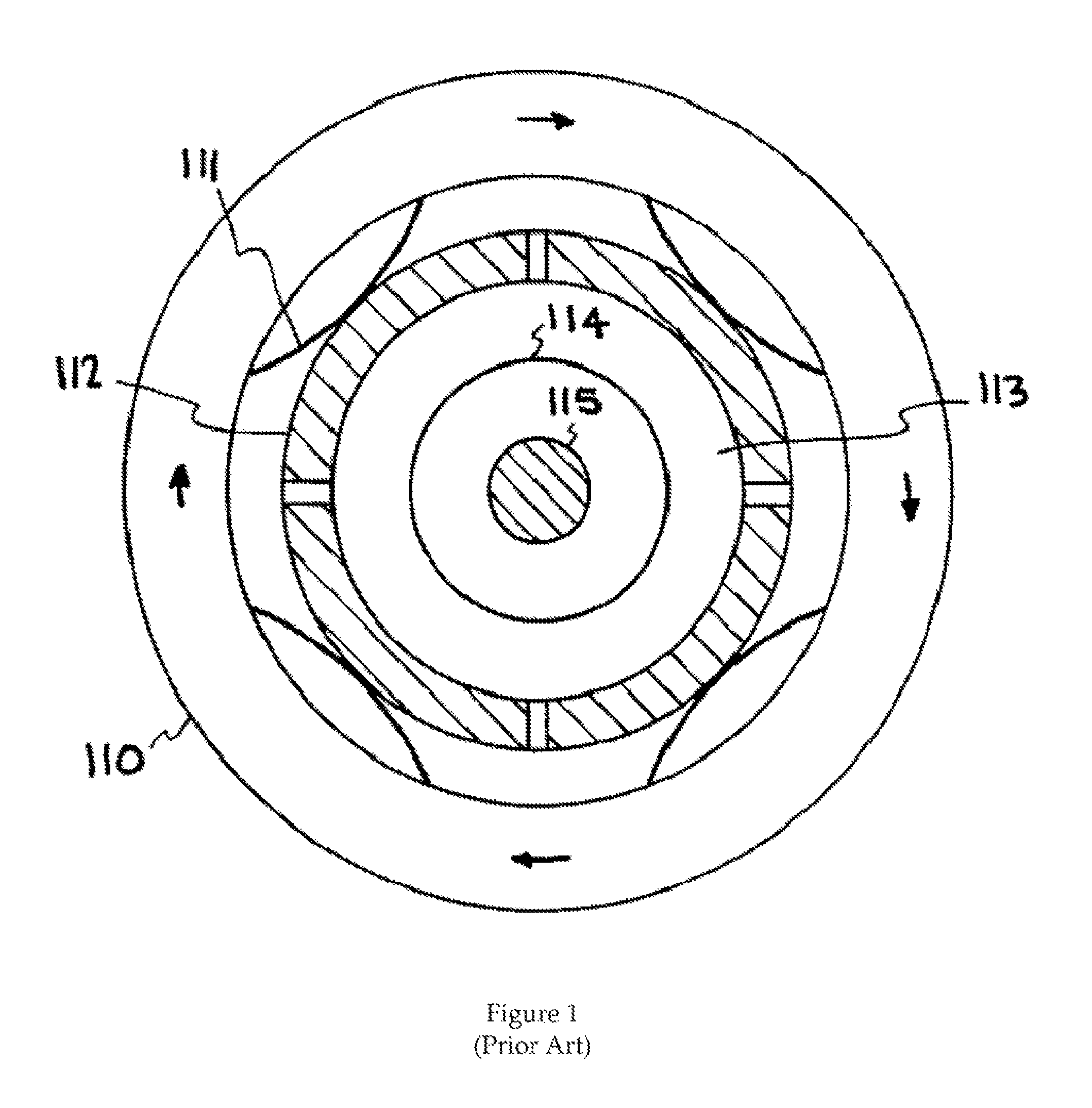
[0022]It is required for a Dynamically stable magnetic suspension / bearing system to operate successfully that mechanical or other means be provided to maintain stability when the rotating element is at rest, or when rotating below a low critical speed determined by the design. To accomplish this end various elements can be used, whereby centering elements act below a critical speed, and are thereafter disengaged, for example by centrifugal action. A prior art centrifugally disengaging mechanical bearing is shown schematically in FIG. 1. It is comprised of an outer (rotating) element 110, spring elements 111, and retainer quadrants 112. Retainers 112 remain in contact with the outer race 113 of a ball bearing, the inner race 114 of which is non-rotating and which is held in position by shaft 115. As shown, a ball bearing acts on the rotating element at zero or slow speeds, and then is disengaged by the action of spring-like elements 111 that expand under the influence of centrifugal ...


PUM

PropertyMeasurementUnit
critical speedaaaaaaaaaa
speedaaaaaaaaaa
tensionaaaaaaaaaa

Abstract

Centrifugally decoupling mechanical bearing systems provide thin tensioned metallic ribbons contained in a support structure. This assembly rotates around a stationary shaft being centered at low speeds by the action of the metal ribbons. Tension springs are connected on one end to the ribbons and on the other end to the support structure. The ribbons pass through slots in the inner ring of the support structure. The spring preloading thus insures contact (or near-contact) between the ribbons and the shaft at rotation speeds below the transition speed. Above this speed, however, the centrifugal force on the ribbons produces a tensile force on them that exceeds the spring tensile force so that the ribbons curve outward, effectively decoupling them from mechanical contact with the shaft. They still remain, however, in position to act as a touchdown bearing in case of abnormally high transverse accelerations.

Description

CROSS-REFERENCE TO RELATED APPLICATIONS[0001]This application claims the benefit of U.S. Provisional Patent Application No. 61 / 350,340 titled “A Centrifugally Decoupling Touchdown Bearing,” filed Jun. 1, 2010, incorporated herein by reference.STATEMENT REGARDING FEDERALLY SPONSORED RESEARCH OR DEVELOPMENT[0002]The United States Government has rights in this invention pursuant to Contract No. DE-AC52-07NA27344 between the U.S. Department of Energy and Lawrence Livermore National Security, LLC, for the operation of Lawrence Livermore National Laboratory.BACKGROUND OF THE INVENTION[0003]1. Field of the Invention[0004]The present invention relates to passive magnetic bearings, and more specifically, it relates to techniques for stabilizing such bearings as the bearing rotates at a rate that is less than the transition speed where the bearing is dynamically stable.[0005]2. Description of Related Art[0006]In the employment of ambient-temperature passive magnetic bearings based on the teac...

Claims


Application Information

Patent Timeline
Patent Type & Authority Patents(United States)
IPC IPC(8): H02K7/09B21D53/10F16C17/02
CPCF16C41/001F16C32/0408F16C2361/55Y10T29/49636
Inventor POST, RICHARD, F.
Owner LAWRENCE LIVERMORE NAT SECURITY LLC
Why Eureka
Try Eureka