Purge/fill valve with a main valve portion aligned with a tee

a technology of purge valve and tee, which is applied in the field of valves, can solve the problems of inefficiency and malfunction of the system, pressure differentials that can affect the operation of the rest of the system, and the method, while functional, is far from ideal

Active Publication Date: 2014-07-08
NIBCO INC
View PDF34 Cites 10 Cited by
  • Summary
  • Abstract
  • Description
  • Claims
  • Application Information

AI Technical Summary

Benefits of technology

[0007]Embodiments of the present invention provide improvements over historical systems and methods for purging hydronic systems by combining un-obstructive flow pattern of a ball valve and positive shutoff characteristics of a ball valve with fewer connection joints of the purge and fill valve assembly to alleviates the detriments such as internal flow restriction, incomplete shutoff and additional leak paths which are prevalent in the current systems and methods.
[0008]An illustrative embodiment of the present invention which is useful in purging hydronic systems provides a purge and fill valve which utilizes three ball valves that are combined into one valve assembly. The valve has a main ball and two valves that communicate from the main valve to an external connection (i.e., drain and fill connections). When the main ball is closed, and the two valves for external communication are opened, the hydronic system can be conveniently and completely emptied and filled from one location. New fluid can be introduced and push out the old fluid, all at one time. The system does not need to be fully emptied and then filled; a two stepped process, rather this is all done in one step.

Problems solved by technology

Because hydronic heating and cooling systems rely on the flow of water through the pipes, the presence of air bubbles or pockets within the piping can lead to inefficiency and malfunction of the system.
The use of such valves can lead to pressure differentials that can affect the operation of the remainder of the system.
This method, while functional, is far from ideal.
Further, disadvantageously, the check valve typically does not provide for complete shutoff and during normal operation of the system the check valve offers some internal flow restriction.

Method used


Image

  • Purge/fill valve with a main valve portion aligned with a tee
  • Purge/fill valve with a main valve portion aligned with a tee
  • Purge/fill valve with a main valve portion aligned with a tee

Examples


Embodiment Construction

[0027]Detailed embodiments of the present invention are disclosed herein, however, it is to be understood that the disclosed embodiments are merely exemplary of the invention, which may be embodied in various forms. Therefore, specific functional or structural details disclosed herein are not to be interpreted as limiting, but merely as a basis for the claims and as a representative basis for teaching one skilled in the art to variously employ the present invention in virtually any appropriately detailed embodiment.

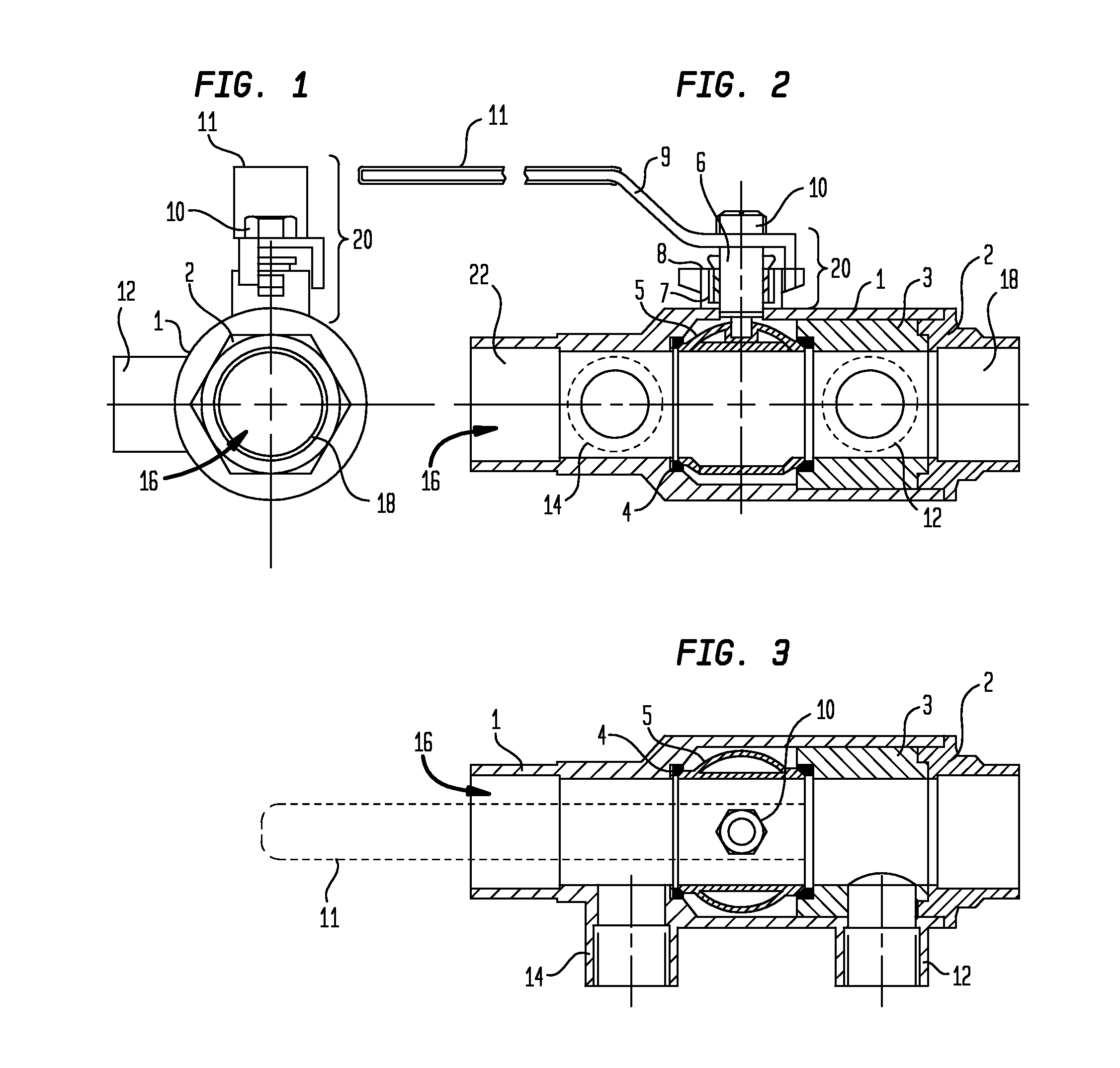
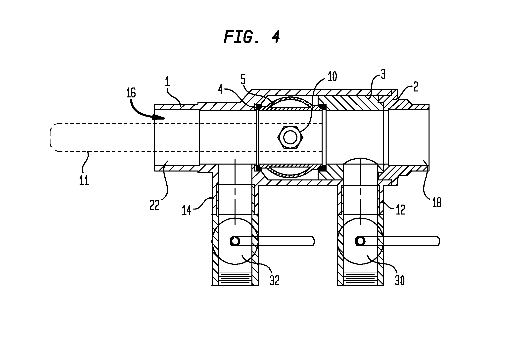
[0028]Turning to FIG. 1, an axial view of an embodiment in accordance with the present invention is shown. A valve body 1 defines a flow channel 16 that extends axially through the valve body 1 from a first primary loop port 18 to a second primary loop port. The valve body 1 also defines a first secondary loop port 12 and a second secondary loop port (not shown). An end cap 2 is affixed to the valve body 1 at the first primary loop port 18. An actuator 20 extends from the...


PUM


Abstract

A purge valve comprising a valve body having a first primary loop port, a second primary loop port, a first secondary loop port and a second secondary loop port is provided. The secondary loop ports are disposed at respective ends or a linear secondary loop portion of the valve body. A primary loop portion of the valve body is formed by a pair of closely spaced tees extending from the secondary loop portion. At least one main valve portion is disposed in a first one of the tees. A drain / venting valve portion extends from the main valve portion. A portion of the secondary loop portion between the tees is shared with the primary loop portion in which flow in a primary loop and a secondary loop are hydraulically separated. A second drain / venting valve portion may be provided in a second one of the tees.

Description

CROSS REFERENCE TO RELATED APPLICATIONS[0001]This is a continuation in part (CIP) of U.S. patent application Ser. No. 11 / 929,002 filed on Oct. 30, 2007 which is a CIP of U.S. patent application Ser. No. 11 / 648,376 filed on Dec. 29, 2006 which claims the benefit of U.S. Provisional Patent Application No. 60 / 756,007, filed on Jan. 4, 2006, the contents of which being incorporated herein by reference in its entirety.FIELD OF INVENTION[0002]The present invention relates to valves, particularly to a primary / secondary loop purge valves.BACKGROUND OF INVENTION[0003]Primary / secondary (“P / S”) piping systems are used to isolate the pressure differential established by a pump from those established by other pumps in the same system. P / S piping allows any pump in the system to operate with virtually no tendency to induce flow, or even disturb flow, in other loops. P / S piping systems have become increasingly popular in many commercial and residential plumbing systems, such as hydronic heating an...

Claims


Application Information

Patent Timeline
Patent Type & Authority Patents(United States)
IPC IPC(8): F16K5/06F16K11/22F16K24/02
CPCY10T137/87249F16K5/0605Y10T137/8782F16K24/02F16K27/067F16K11/20
Inventor RECK, MICHAEL, E.
Owner NIBCO INC
Why Eureka
Try Eureka