Near boiler piping apparatus

a piping apparatus and boiler technology, applied in the direction of pipe protection against corrosion/incrustation, fluid pressure control, multiple way valves, etc., can solve the problems of inefficiency and system malfunction, pressure differentials that can affect the operation of the rest of the system, and the method, while functional, is far from ideal

Active Publication Date: 2010-12-23
NIBCO INC
View PDF33 Cites 12 Cited by
  • Summary
  • Abstract
  • Description
  • Claims
  • Application Information

AI Technical Summary

Benefits of technology

[0007]Embodiments of the present invention provide improvements over historical systems and methods for purging hydronic systems by combining un-obstructive flow pattern of a ball valve and positive shutoff characteristics of a ball valve with fewer connection joints of the purge and fill valve assembly to alleviates the detriments such as internal flow restriction, incomplete shutoff and additional leak paths which are prevalent in the current systems and methods.
[0008]An illustrative embodiment of the present invention which is useful in purging hydronic systems provides a purge and fill valve which utilizes three ball valves that are combined into one valve assembly. The valve has a main ball and two valves that communicate from the main valve to an external connection (i.e., drain and fill connections). When the main ball is closed, and the two valves for external communication are opened, the hydronic system can be conveniently and completely emptied and filled from one location. New fluid can be introduced and push out the old fluid, all at one time. The system does not need to be fully emptied and then filled; a two stepped process, rather this is all done in one step.

Problems solved by technology

Because hydronic heating and cooling systems rely on the flow of water through the pipes, the presence of air bubbles or pockets within the piping can lead to inefficiency and malfunction of the system.
The use of such valves can lead to pressure differentials that can affect the operation of the remainder of the system.
This method, while functional, is far from ideal.
Further, disadvantageously, the check valve typically does not provide for complete shutoff and during normal operation of the system the check valve offers some internal flow restriction.

Method used


Image

  • Near boiler piping apparatus
  • Near boiler piping apparatus
  • Near boiler piping apparatus

Examples


first embodiment

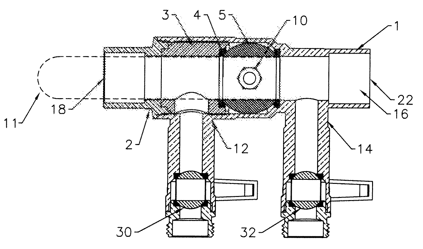
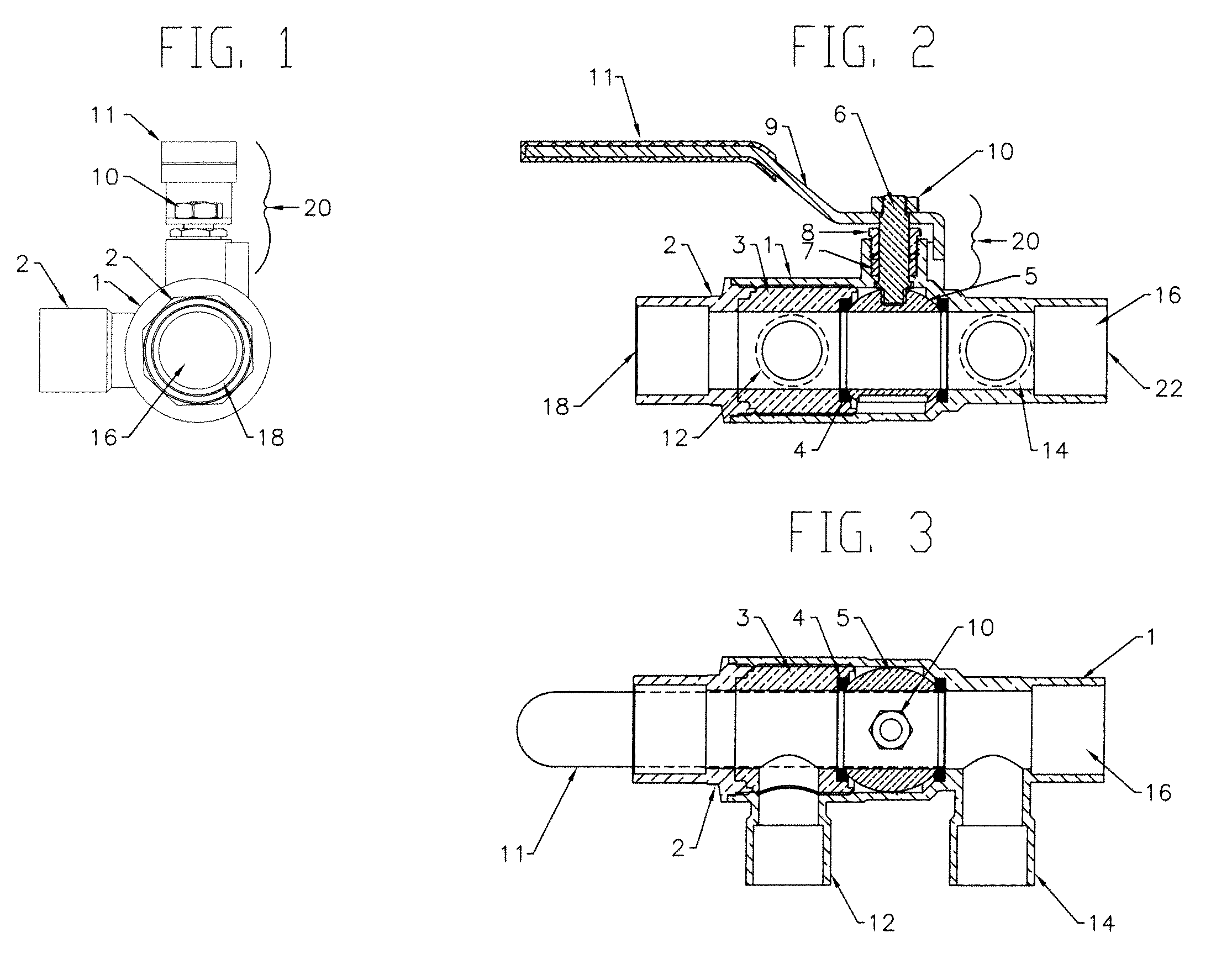
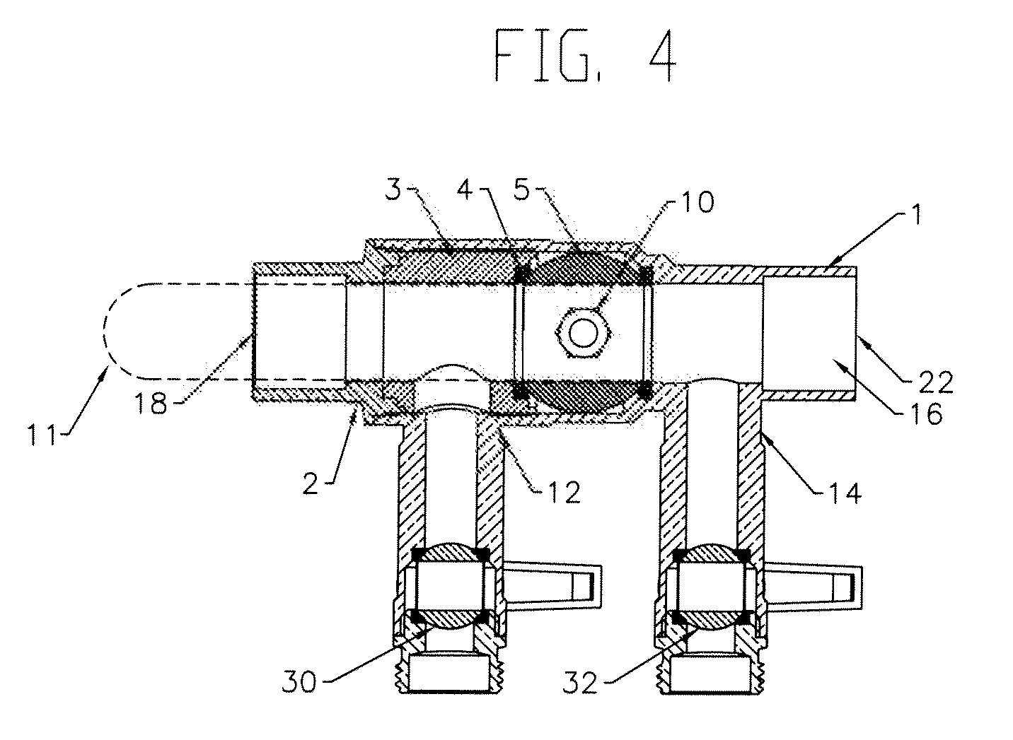
[0042]Turning now to FIG. 2 and FIG. 3, cut-away views of the present invention are shown. FIG. 2 depicts the embodiment from a side-view, while FIG. 3 depicts the embodiment from a top-view. A valve body 1 defines a flow channel 16 axially though the valve from the first primary loop port 18 to the second primary loop port 22. The first secondary loop port 12 and the second secondary loop port 14 are also in fluid communication with the flow channel 16. The end cap 2 is disposed into the valve body 1 and mated with a seat retainer 3. The actuator 20 extends from the valve body 1 containing a stem 6, a stem seal 7 and a packing gland 8. The actuator 20 also includes a handle 11 that is affixed to the stem 6 with the handle nut 10. The actuator 20 repositions the flow diversion device 5 to alter the flow channels of the valve. The flow diversion device 5 is disposed within the valve body 1 in between the first secondary loop port 12 and the second secondary loop port 14. The flow div...

eighth embodiment

[0090]An implementation of the primary / secondary loop interface apparatus according to the invention in a primary / secondary loop piping system is described with reference to FIG. 22. The primary-secondary loop piping system includes at least one boiler 602 in fluid communication with a primary piping loop 604. At least one primary loop pump 606 is installed in the primary piping loop 604. At least one secondary piping loop 608, 608′, 608″ branches away from the primary loop 604 and returns downstream to the primary loop 608 via a pair of closely spaced tees in a primary-secondary piping loop interface apparatus 500.

[0091]In the primary / secondary loop piping system shown in FIG. 22, each of the primary-secondary piping loop interfaces 500 are substantially identical to those described hereinbefore with reference to FIGS. 20 and 21.

[0092]At least one secondary loop pump 610 is installed in each of the secondary piping loops 608. In each secondary loop 608, the secondary loop pump 610 ...


PUM


Abstract

A near-boiler piping loop apparatus is provided including a primary / secondary piping loop interface apparatus having a unitary construction including a secondary loop shut-off valve, drain valve and drain port in each branch of a secondary loop for connection to a boiler. Supply branch piping and return branch piping connects the interface apparatus to the boiler and provides attachment points for auxiliary plumbing equipment. The apparatus is adapted to connect to pump in variable orientations using rotatable flanges on the interface apparatus and on a wye strainer in the secondary loop supply branch and includes a union fitting attached to the interface apparatus. The union fitting provides a mounting hole for a temperature or pressure gauge.

Description

CROSS REFERENCE TO RELATED APPLICATIONS[0001]This is a continuation of U.S. patent application Ser. No. 12 / 836,248 which is a continuation-in-part (CIP) of U.S. patent application Ser. No. 12 / 753,408 filed on Apr. 2, 2010 which is a continuation-in-part (CIP) of U.S. patent application Ser. No. 12 / 615,547 filed on Nov. 10, 2009 which is a CIP of U.S. patent application Ser. No. 11 / 929,002 filed on Oct. 30, 2007 which is a CIP of U.S. patent application Ser. No. 11 / 648,376 filed on Dec. 29, 2006 which claims the benefit of U.S. Provisional Patent Application No. 60 / 756,007, filed on Jan. 4, 2006. The contents of U.S. patent application Ser. No. 12 / 753,408, U.S. patent application Ser. No. 12 / 615,547, U.S. patent application Ser. No. 11 / 929,002, U.S. patent application Ser. No. 11 / 648,376 and U.S. Provisional Patent Application No. 60 / 756,007 are incorporated herein by reference in their entirety.FIELD OF INVENTION[0002]The present invention relates to primary / secondary loop piping sy...

Claims


Application Information

Patent Timeline
Patent Type & Authority Applications(United States)
IPC IPC(8): F16K11/10
CPCF16K11/22F16K27/067F24D3/10F24D19/083F24D19/088F24D19/1015Y10T137/87909Y10T137/87523Y10T137/87249Y10T137/87917Y10T137/87362Y10T137/8782F24D3/1058F24D3/02F24D3/105F24D19/08F24H9/13
Inventor OLSEN, JASON LARSRECK, MICHAEL
Owner NIBCO INC
Why Eureka
Try Eureka