

Damage Sensors
- Summary
- Abstract
- Description
- Claims
- Application Information
AI Technical Summary
Benefits of technology
Problems solved by technology
Method used
Image

Examples
first embodiment
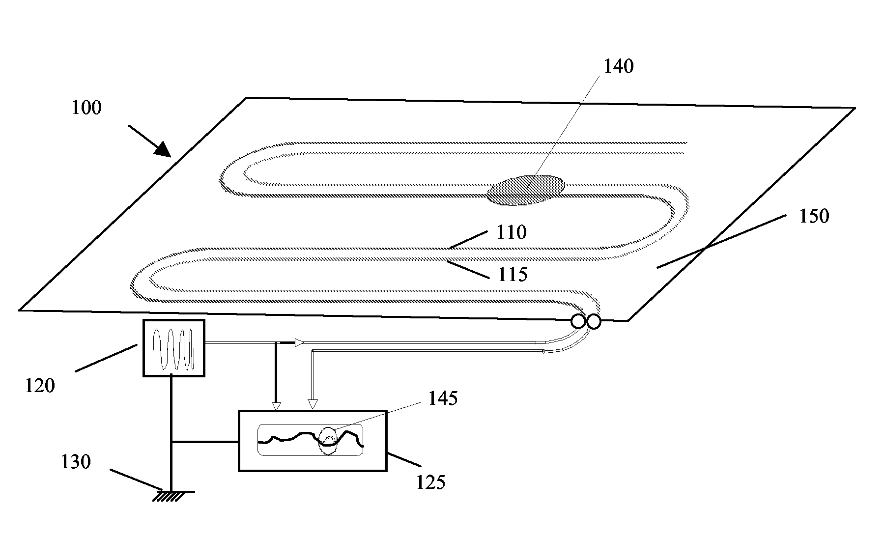
[0026]FIG. 1 schematically shows a damage sensor 100 according to the invention. Damage sensor 100 comprises a probe track 110 and a sense track 115. The probe track 110 and sense track 115 are printed directly onto the structure 150 to be monitored. Structure 150 could be an aircraft airframe, or a ship's hull. The probe track 110 and sense track 115 are electromagnetically coupled by the structure 150. Uniform electromagnetic coupling between the probe track 110 and the sensor track 115 is achieved by arranging tracks 110, 115 on the surface of structure 150 in a parallel configuration such that they are separated by a gap of uniform width along their length. If it is desired to monitor the whole of structure 150, the tracks 110, 115 should be further arranged to extend over substantially the whole of the structure. The term “substantially the whole of the structure”, will be understood by those skilled in the art to mean at least a representative portion of the structure, such th...
third embodiment
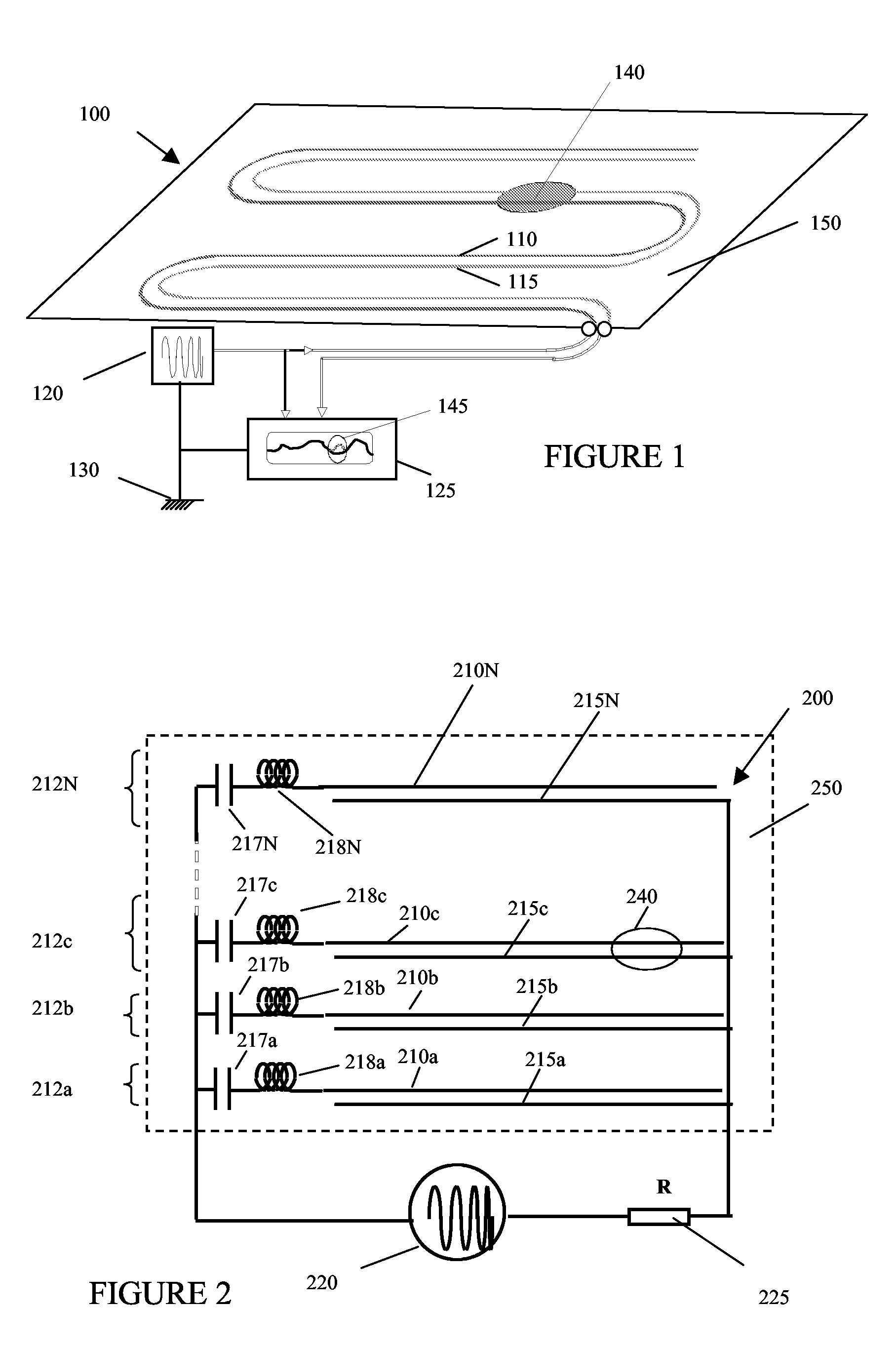
[0033]FIG. 2 shows a damage sensor 200 according to the invention. Damage sensor 200 comprises a number of sensing elements 212a-N. Each sensing element comprises a frequency selector, a probe track 210 and a sense track 215. For example, sensing element 212a comprises a frequency selector, probe track 210a and sense track 215a. The sensing elements are interconnected in parallel, and connected to a signal generator 220 and a signal analyser 225. The frequency selectors comprise inductors 218 and capacitors 217—for example, the frequency selector for sensing element 212b comprises capacitor 217b and inductor 218b. In combination, the inductor and capacitor in each frequency selector form a resonant circuit. Each sensing element is chosen to operate at a distinct frequency, by trimming capacitors 217 and inductors 218 to tune the resonant frequency of each frequency selector. Each sensing element 212 thus operates at the resonant frequency of its frequency selector. For example, an i...
PUM
 Abstract
Description
Claims
Application Information