Damage sensors

a technology of damage sensors and sensors, applied in the direction of electrical/magnetic measurement arrangements, structural/machine measurement, using electrical/magnetic means, etc., can solve the problems of changing the electrical and changing the electromagnetic properties of the structure, etc., to achieve direct sensing, simple and quick manufacturing, and cost-effective

Inactive Publication Date: 2011-05-31
BAE SYSTEMS PLC
View PDF17 Cites 12 Cited by
  • Summary
  • Abstract
  • Description
  • Claims
  • Application Information

AI Technical Summary

Benefits of technology

[0006]It is an object of the invention to at least reduce or partially overcome some of the above-mentioned drawbacks. It is a further object of the invention to provide a damage sensor that is simple and quick to manufacture, cost-effective and directly sensitive to the pressure or occurrence of damage to a structure. It is an object of the present invention to provide a damage sensor that produces an output that is more simple to analyse than that of prior known damage sensors. It is also an object of the invention to provide a damage sensor with fewer electrical connections, and thus enhanced reliability and scalability, than prior known damage sensors.
[0007]In broad terms, the present invention resides in the concept of using a structure to electromagnetically couple two conducting tracks, allowing damage to the structure to be sensed by measuring the degree of electromagnetic coupling between the two tracks. This concept finds application in damage detection sensors according to embodiments of the invention, in methods of manufacture of such damage sensor, and in methods of sensing damage to a structure. Damage sensors according to embodiments of the invention are directly sensitive to the characteristics of the structure being monitored, and can be fabricated rapidly and cheaply by using, for example, direct-write techniques to print tracks on to a structure.
[0008]In accordance with a first aspect of the present invention, there is provided a damage sensor for sensing damage to a structure, the damage sensor comprising a probe track, a sense track, and a signal generator operable to input a probe signal to the probe track, the probe track and the sense track being electromagnetically coupled by the structure such that the probe signal induces, in dependence on the degree of electromagnetic coupling between the probe track and the sense track, a sensed signal in the sense track. The term “electromagnetically coupled”, when used herein, is intended to be construed broadly to include, for example, coupling by electromagnetic waves, such as optical signals, radio-frequency signals or terahertz-frequency signals; or coupling by purely electric signals through conduction and capacitive effects. Because the sensed signal is related to the degree of electromagnetic coupling between the probe track and the sense track, and this electromagnetic coupling is due to the structure, the damage sensor is directly sensitive to the electromagnetic properties of the structure. Therefore, any damage that changes the electromagnetic properties of the structure is visible in the sensed signal. This direct sensitivity is advantageous in that it allows simple analysis techniques (such as comparing a sensed signal to a reference signal, measured when the structure was known to be undamaged) to be reliably used.

Problems solved by technology

The damage sensor is thus sensitive to, for example, mechanical damage that causes physical disruption to the structure, thereby changing its electrical and electromagnetic properties; and to chemical damage, due, for example, to chemical influences, such as the ingress of moisture or other foreign materials, that degrade the integrity of the structural material and thereby change the electromagnetic properties of the structure.
Damage such as, for example, the presence of cracks, delamination in laminate structures, infusion of foreign matter, or the presence of corrosion will also be visible in the sensed signal.

Method used


Image

  • Damage sensors
  • Damage sensors

Examples


first embodiment

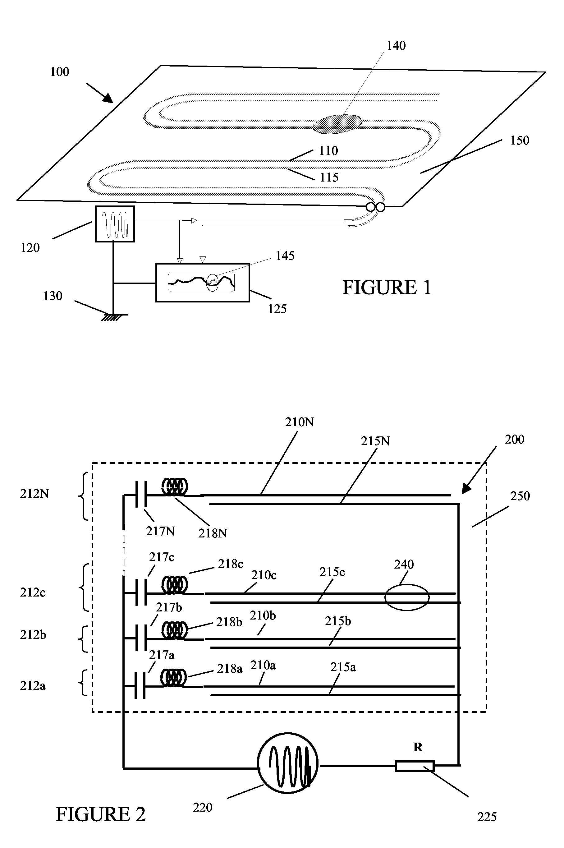
[0026]FIG. 1 schematically shows a damage sensor 100 according to the invention. Damage sensor 100 comprises a probe track 110 and a sense track 115. The probe track 110 and sense track 115 are printed directly onto the structure 150 to be monitored. Structure 150 could be an aircraft airframe, or a ship's hull. The probe track 110 and sense track 115 are electromagnetically coupled by the structure 150. Uniform electromagnetic coupling between the probe track 110 and the sensor track 115 is achieved by arranging tracks 110, 115 on the surface of structure 150 in a parallel configuration such that they are separated by a gap of uniform width along their length. If it is desired to monitor the whole of structure 150, the tracks 110, 115 should be further arranged to extend over substantially the whole of the structure. The term “substantially the whole of the structure”, will be understood by those skilled in the art to mean at least a representative portion of the structure, such th...

third embodiment

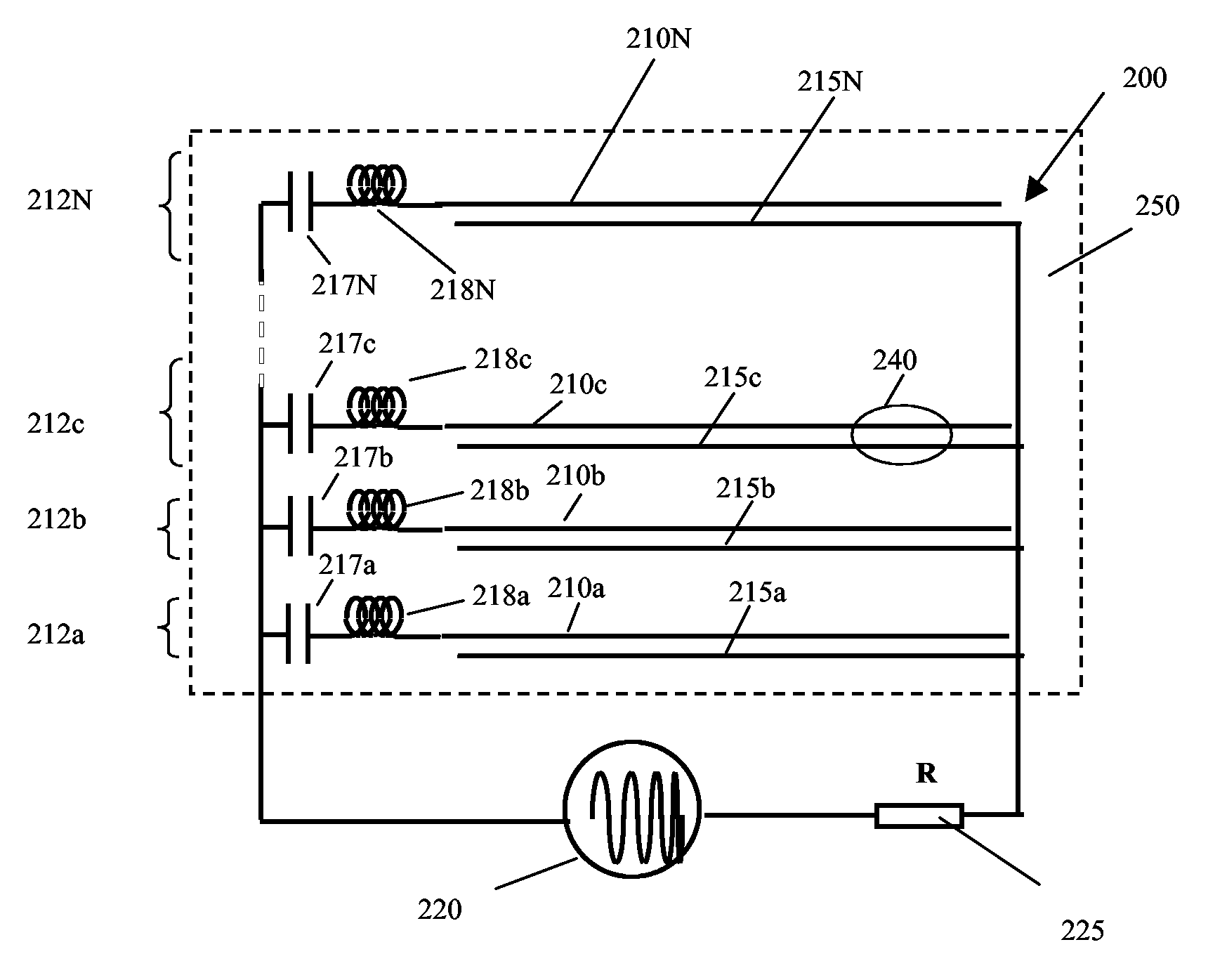
[0033]FIG. 2 shows a damage sensor 200 according to the invention. Damage sensor 200 comprises a number of sensing elements 212a-N. Each sensing element comprises a frequency selector, a probe track 210 and a sense track 215. For example, sensing element 212a comprises a frequency selector, probe track 210a and sense track 215a. The sensing elements are interconnected in parallel, and connected to a signal generator 220 and a signal analyser 225. The frequency selectors comprise inductors 218 and capacitors 217—for example, the frequency selector for sensing element 212b comprises capacitor 217b and inductor 218b. In combination, the inductor and capacitor in each frequency selector form a resonant circuit. Each sensing element is chosen to operate at a distinct frequency, by trimming capacitors 217 and inductors 218 to tune the resonant frequency of each frequency selector. Each sensing element 212 thus operates at the resonant frequency of its frequency selector. For example, an i...


PUM


Abstract

A damage sensor comprises a probe track, a sense track, and a signal generator operable to input a probe signal to the probe track. The probe track and the sense track are electromagnetically coupled by a structure on which they are provided, such that the probe signal induces, in dependence on the degree of electromagnetic coupling between the probe track and the sense track, a sensed signal in the sense track. The magnitude, phase and frequency of the sensed signal can be analysed in order to determine whether and where damage has occurred to the structure.

Description

FIELD OF THE INVENTION[0001]The present invention concerns improvements relating to damage sensors. More particularly, but not exclusively, the present invention relates to damage sensors for detecting the presence and occurrence of damage to a broad variety of structures such as aircraft, ships and bridges.BACKGROUND[0002]Structures such as aircraft airframes, ships' hulls, and bridges require regular inspections to check for damage. Inspections are currently usually performed manually according to a schedule. These scheduled inspections are precautionary, and, often, no damage is found. Such inspections are very time consuming and thus costly, since the structure will be out of use whilst the inspection is carried out. However, they are necessary since the consequences of structural failure can be catastrophic.[0003]A number of damage or defect sensor systems are currently being developed. These systems aim to eliminate costly manual technology by enabling structures to perform ‘s...

Claims


Application Information

Patent Timeline
Patent Type & Authority Patents(United States)
IPC IPC(8): G01M5/00
CPCG01M5/0033G01M11/083G01M5/0091G01N17/02
Inventor FOOTE, PETER DAVID
Owner BAE SYSTEMS PLC
Why Eureka
Try Eureka