Additive manufacturing method using focused light heating source

Active Publication Date: 2015-11-19
EUROPEAN SPACE AGENCY
View PDF63 Cites 20 Cited by
  • Summary
  • Abstract
  • Description
  • Claims
  • Application Information

AI Technical Summary

Benefits of technology

[0043]By using a method according to the present invention, it will be possible to manufacture the components in space as and when they are needed rather than to transport a complete repository of tools and parts in case they might be urgently required. Hereby the payload can be significantly decreased. The present invention may therefore be particularly advantageous in sp

Problems solved by technology

However, although very manipulative, these power sources are rather expensive and require high levels of maintenance and safety procedures.
Potential use of these methods for medium and large sized components would take long processing times and therefore are prohibitively expensive.
Furthermore, these methods are not suitable for obtaining low surface roughness, and finishing machining is therefore normally

Method used


Image

  • Additive manufacturing method using focused light heating source
  • Additive manufacturing method using focused light heating source
  • Additive manufacturing method using focused light heating source

Examples


Example

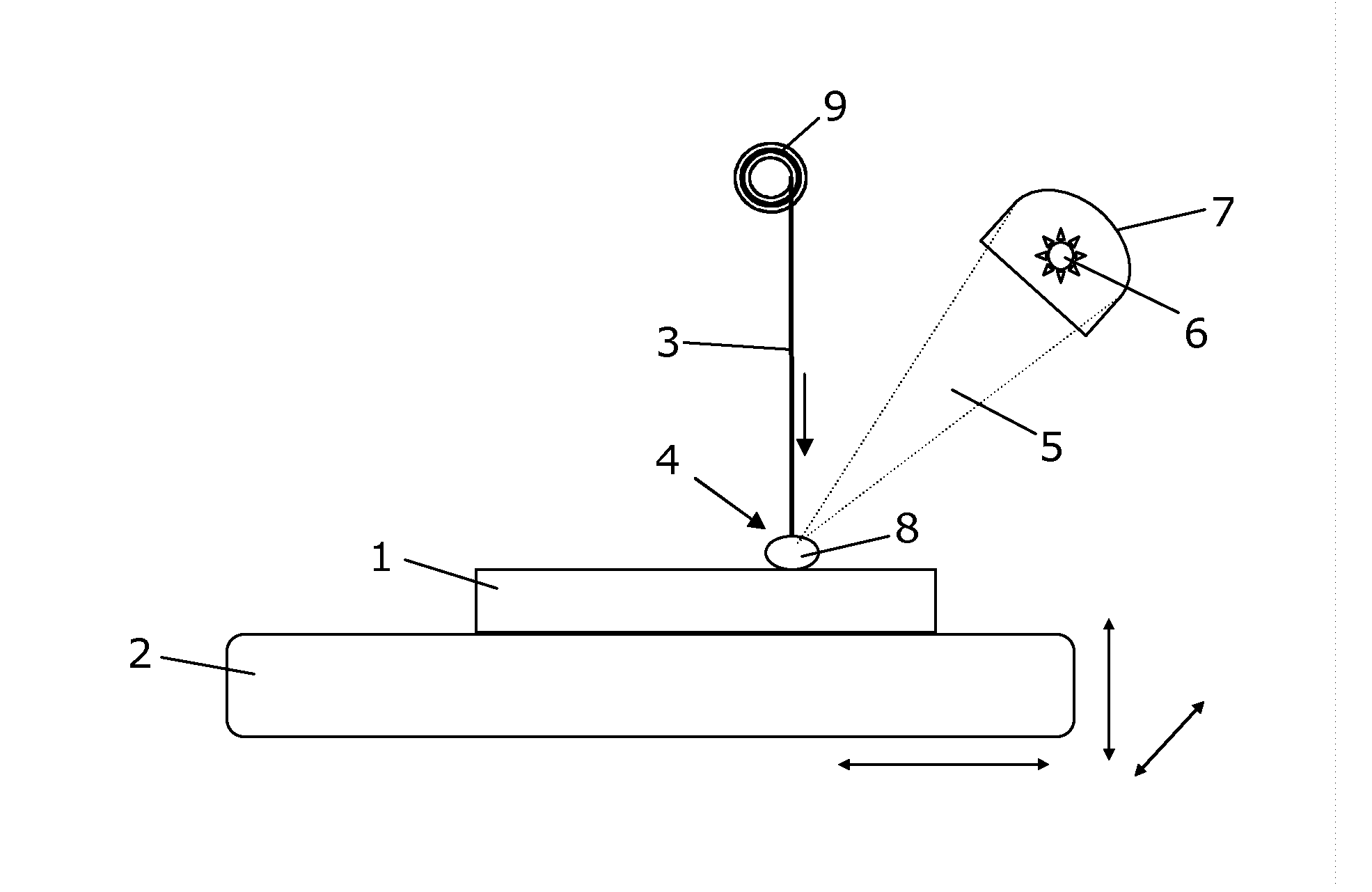
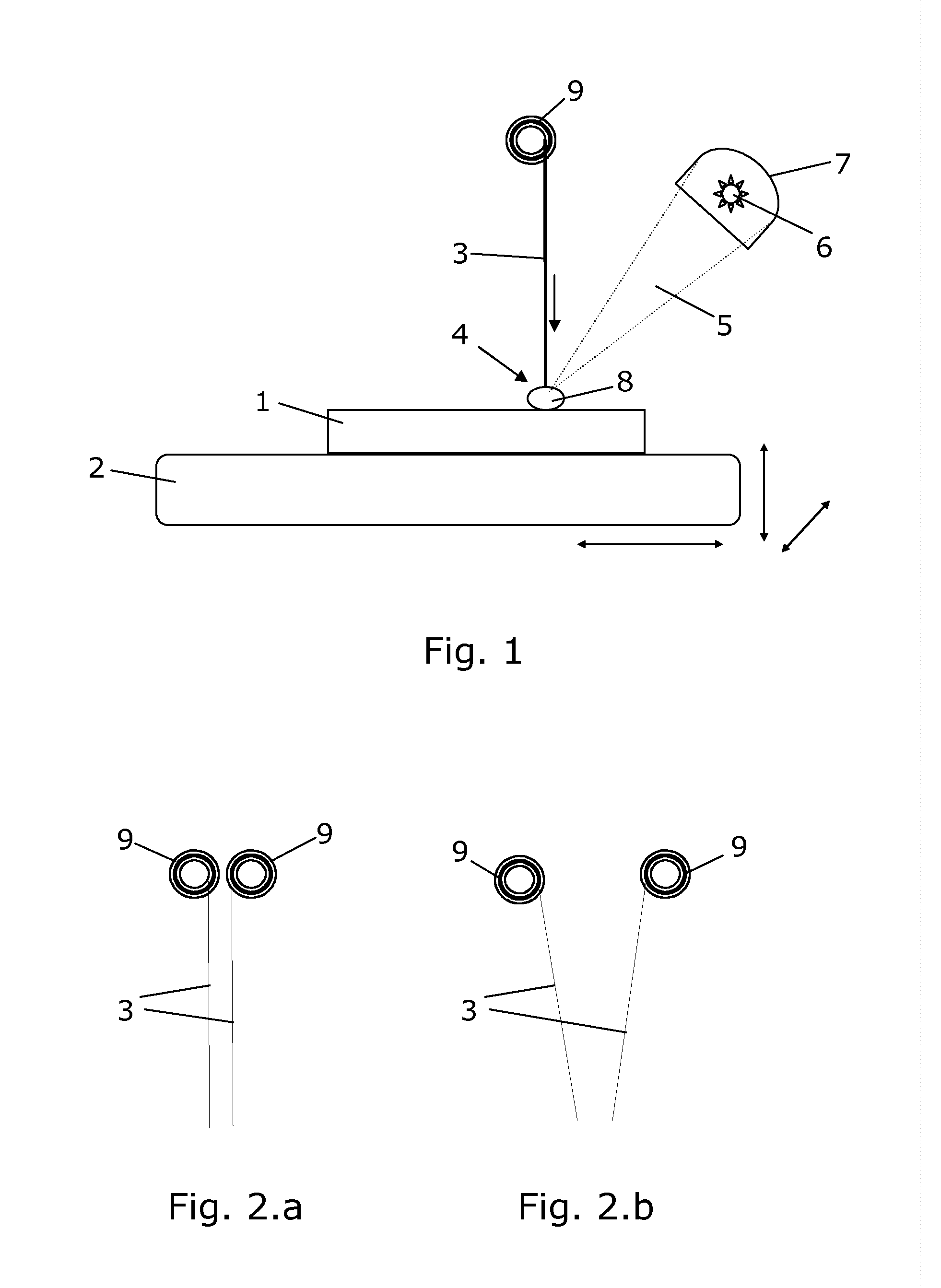
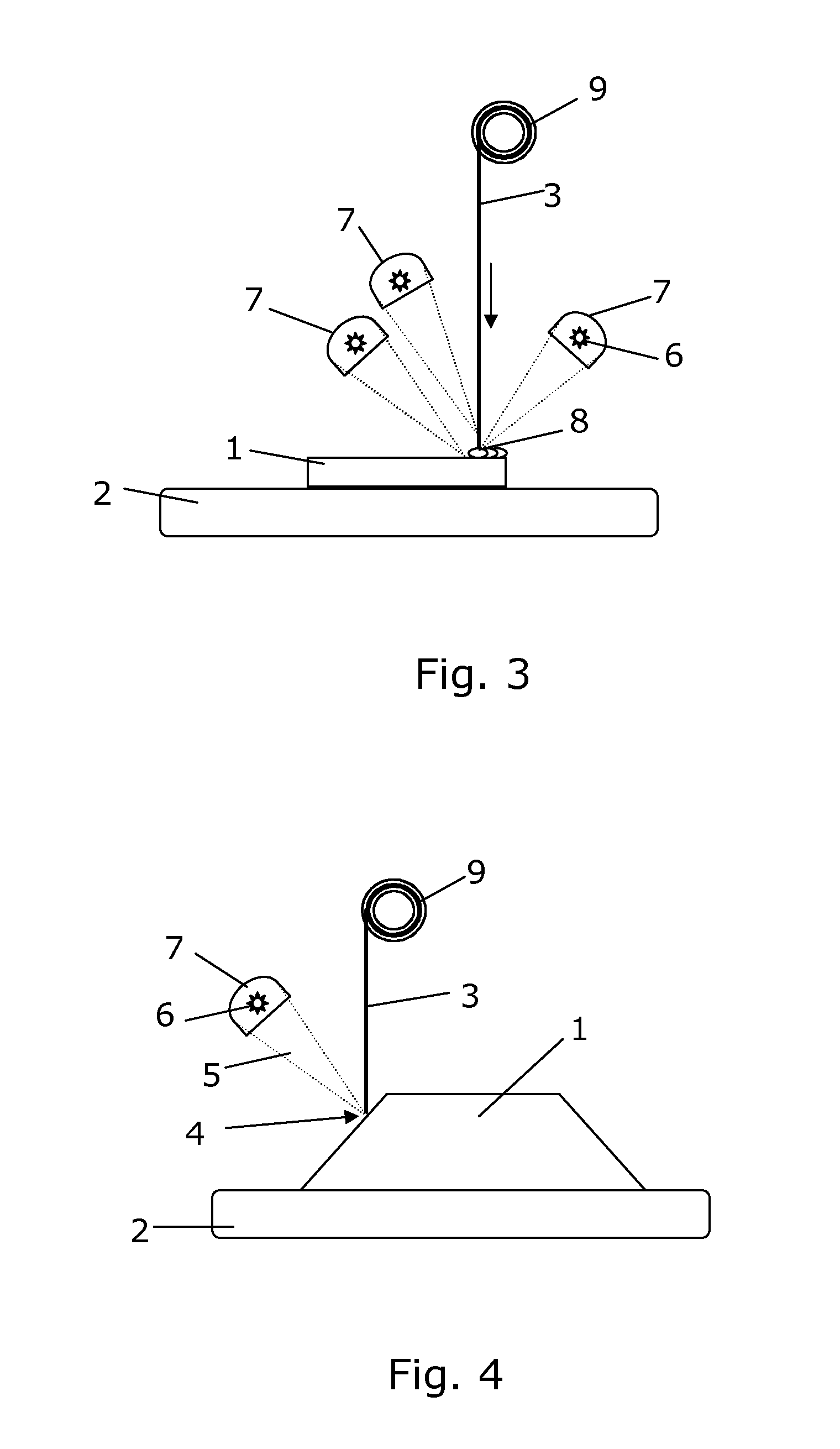
[0054]FIG. 1 shows schematically a method of manufacturing a component 1 by additive manufacturing according to the present invention. The component 1 is being manufactured on a work surface 2 which in the illustrated embodiment can be moved in three dimensions, as indicated by arrows, while the rest of the system is not moved. In the figure, the at least one deposition material from which the component is to be composed is arranged above the work surface. The deposition material 3 is shown in the form of one wire 3 in this figure. The deposition material is advanced to a localized deposition area 4 where it is added to the component 1 being manufactured. This deposition is obtained by focusing at least one light beam 5 emitted from at least one heating source 6 in the deposition area 4 so that the deposition material 3 is deposited for building up the component 1. In the illustrated embodiment, the work surface is moved in relation to the light beam and the deposition material alon...


PUM

PropertyMeasurementUnit
Sizeaaaaaaaaaa
Poweraaaaaaaaaa
Areaaaaaaaaaaa

Abstract

The present invention relates to a method of manufacturing a component 1 by additive manufacturing. The method comprises providing a work surface 2 on which the component 1 is to be manufactured, and providing at least one deposition material 3 from which the component 1 is to be composed. The deposition material, typically in the form of wire, is advanced to a localized deposition area 4 where it is added to the component 1 being manufactured. The method further comprises focusing at least one light beam 5 of incoherent light emitted from at least one heating source 6 in the deposition area 4 so that the deposition material 3 is deposited for building up the component 1. At least one light focusing mirror 7 and/or lens 11 is used to focus the incoherent light in the deposition area 4. The invention further relates to the use of such a method in space, such as on a space station, on a space craft or on parabolic flights for testing.

Description

CROSS-REFERENCE TO RELATED APPLICATIONS[0001]This application is the U.S. national stage application of International Patent Application No. PCT / EP2012 / 076709, filed Dec. 21, 2012, which is hereby incorporated by reference.FIELD OF THE INVENTION[0002]The present invention relates to manufacturing of components by additive manufacturing and in particular to methods comprising use of incoherent light to melt or soften the deposition material from which the component is to be composed.BACKGROUND OF THE INVENTION[0003]Currently used net-shape additive manufacturing techniques build alloy components layer by layer by melting powders or wires using a laser or electron beam power source. However, although very manipulative, these power sources are rather expensive and require high levels of maintenance and safety procedures. They are also mainly suited to manufacturing of small scale components because of the small spot size of the energy beam that is normally used for greater accuracy dur...

Claims


Application Information

Patent Timeline
IPC IPC(8): B23K28/00B23K35/30B23K35/32B23K35/02B23K35/28
CPCB23K28/00B23K35/0261B23K35/286B23K35/284B23K35/325B33Y10/00B23K35/3033B23K35/3046B23K35/302B23K35/30B23K35/3053B23K1/0053B29C64/153Y02P10/25B22F12/33B22F10/362B22F12/37B22F12/55B22F10/32B22F12/13B22F12/44B22F10/36B22F10/25B22F12/42
Inventor JARVIS, DAVID JOHNVOICE, WAYNE ERIC
Owner EUROPEAN SPACE AGENCY
Why Eureka
Try Eureka