Glove having a cuffed portion

a technology of cuffs and gloves, applied in gloves, clothing, clothing, etc., can solve the problems of cuffs that are difficult to maintain in cuffs, liquid escaping from the cuffs, and contact with the wearer, so as to facilitate the application and removal of the wearer, the effect of easy disengagemen

Active Publication Date: 2009-01-27
PLAYTEX PROD INC +1
View PDF99 Cites 21 Cited by
  • Summary
  • Abstract
  • Description
  • Claims
  • Application Information

AI Technical Summary

Benefits of technology

[0009]It is an object of the present invention to provide a glove having a cuff portion that can easily be applied and removed from the wearer and does not easily become disengaged from a cuffed position.
[0010]It is another object of the present invention to provide a glove having a cuff portion and an arm covering portion to protect a wearer's arm from liquid.
[0013]It is a yet still another object of the present invention to provide a glove with a cuff portion that can be easily and quickly be manufactured in a cost effective manner.

Problems solved by technology

The glove of the prior art is deficient in its operation.
The inventor has found that through consumer testing the glove of Vrissimdjis has a cuff portion that is difficult to maintain in a cuffed shape.
Also, the glove of Vrissimdjis results in becoming easily unfolded and liquid escaping from the cuffed portion and contacting the wearer.
The cuff portion of the glove of Vrissimdjis is difficult to hold in a cuffed position due to the overall dimensions or size, shape, and weight of the glove.
For example, if a consumer touches the cuffed portion at an edge of, for example, a dishwasher, the cuffed portion will become undone and liquid may contact the wearer.
Also, the cuffed portion of Vrissimdjis is generally awkward, and, thus, not comfortable when worn in the cuffed portion.

Method used


Image

  • Glove having a cuffed portion
  • Glove having a cuffed portion
  • Glove having a cuffed portion

Examples


fourth embodiment

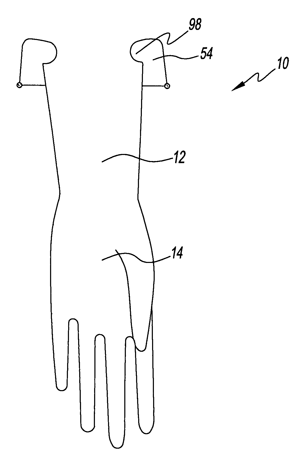
[0084]the glove 10 indicates to the wearer a location where to fold the glove 10 to form the cuff portion 54. Referring to FIGS. 6 and 6A, the cuff portion 54 has a first thickness 66, and the arm covering portion 12 has a second thickness 68. Preferably in this embodiment, the second thickness 68 is greater than the first thickness 66. The difference from the first thickness 66 to the second thickness 68 is a detector. The difference gives the wearer a tactile feedback to detect a predetermined location where to fold the cuff portion 54 relative to the arm covering portion 12.

[0085]Also, the cuff portion 54 has a first arm 70 and a second arm 72. The first arm 70 and the second arm 72 both are connected to the arm covering portion 12. The first arm 70 and the second arm 72 are connected at a base 74 thereof adjacent to an opening of the glove 10. The first arm 70 is preferably disposed at an angle relative to a lateral side of the arm covering portion 12. Preferably, the angle is i...

fifth embodiment

[0086]FIG. 7 shows the cuffed portion of the glove 10 in which the first arm 72 and the second arm 74 of the cuff portion 54 are preferably substantially adjacent to the arm covering portion 12 to form the space 36 therebetween for allowing liquid to collect therein. Again, the noticeable thickness difference from the first thickness 66 to the second thickness 68 gives the wearer a tactile feedback as to the location where to fold the cuff portion 54 relative to the arm covering portion 12. Referring to FIG. 7A, the cuff portion 54 preferably is disposed at an angle relative to an outer plane that is parallel to the outer surface of the arm covering portion 12. This angle is variable and may be less than ninety degrees as shown, preferably an acute or narrow angle, less than forty-five degrees, or at about forty degrees.

sixth embodiment

[0087]FIG. 8 shows the cuffed portion of the glove 10. The glove 10 preferably has a first tubular section 78 and a second tubular section 80. Preferably, the first tubular section 78 has a first diameter 82 and is connected to the second tubular section 80. The second tubular section 80 preferably has a second diameter 84 that is greater than the first diameter 82 to form an exterior edge 86. The exterior edge 86 of the second tubular section 80 preferably extends outwardly therefrom. The exterior edge 86 obstructs liquid. In this manner, any liquid that traverses from the hand covering portion 14 will contact the exterior edge 86 of the second tubular section 80 and deflect outwardly from the glove 10. This exterior edge 86 also acts as a fold indicator to assist the wearer with a location where to fold the glove 10. The first tubular section 78 and the second tubular section 80 form an angle relative to one another. This angle can vary and be 90 degrees or higher or any angle in ...


PUM

PropertyMeasurementUnit
radiusaaaaaaaaaa
diameteraaaaaaaaaa
length l1aaaaaaaaaa

Abstract

The present invention provides a glove for a wearer. The glove has a hand covering portion and an arm covering portion connected to the hand covering portion. The arm covering portion has a number of segments with each connected to one another by a pivot. The arm covering portion in a first position covers and protects the wearer. The arm covering portion in a second position forms an obstruction to prevent a liquid from contacting the wearer with the obstruction trapping the liquid therein.

Description

CROSS REFERENCES TO RELATED PATENT APPLICATIONS[0001]The present application is claiming priority of U.S. Provisional Patent Application Ser. No. 60 / 611,979 filed on Sep. 22, 2004 and U.S. Provisional Patent Application Ser. No. 60 / 630,169 filed on Nov. 22, 2004, with the entire contents of each incorporated by reference herein.BACKGROUND OF THE INVENTION[0002]1. Field of the Invention[0003]The present invention relates to a glove for covering a hand and an arm of a wearer. More particularly, the present invention relates to a glove that has a cuffed or conical segment having a diameter wider than the glove itself. The cuffed or conical segment will create an obstruction to shield the wearer from being contacted by a liquid.[0004]2. Description of the Related Art[0005]Gloves having cuffs are known in the art. One such glove is disclosed in U.S. Pat. No. 6,249,917 B1 to Vrissimdjis. Vrissimdjis discloses a glove. The glove has a tubular sleeve portion and a cuff portion connected to ...

Claims


Application Information

Patent Timeline
Patent Type & Authority Patents(United States)
IPC IPC(8): A41D19/00
CPCA41D19/0044A41D19/0062
Inventor KNUTH, ROSEMARY F.RANDOLPH, ROSS STEVENHOURIHAN, JOSEPH C.MEROVITZ, GERALD
Owner PLAYTEX PROD INC
Why Eureka
Try Eureka