Submersible pump assembly

a technology of submersible pumps and components, applied in the direction of pump control, positive displacement liquid engine, non-positive displacement fluid engine, etc., can solve the problem of providing no external control or monitoring possibilities at all

Active Publication Date: 2015-08-11
GRUNDFOS MANAGEMENT AS
View PDF10 Cites 11 Cited by
  • Summary
  • Abstract
  • Description
  • Claims
  • Application Information

AI Technical Summary

Benefits of technology

[0006]With regard to this state of the art, it is an objective of a preferred embodiment of the present invention to provide a simplified submersible pump assembly which may be connected with few lead connections and moreover provides the possibility of monitoring the operation of the submersible pump assembly at ground level, for example outside the pump sump or borehole, into which the drive motor is submerged.
[0010]Preferably, at least one sensor connected to the control device is present. This sensor is preferably likewise submerged into the fluid to be delivered and further preferably likewise integrated into the submersible part of the submersible pump assembly, for example the part formed by the submersible pump, drive motor and control device. Such a sensor may for example be a level switch which is used in order to switch the pump on and / or off in dependence on the fluid level. By way of the arrangement of the control device and of the sensor in the fluid to be delivered, the effort required for connecting these elements to one another is significantly reduced, since no lead is necessary from the submerged sensor to a control or regulation device arranged outside the fluid.
[0014]Even if the electrical cable is not a mains cable, it is preferably for the control device as well as the display device and / or the communication device to be designed in a manner such that a data transmission in the manner of a data transmission via powerline-communication is effected via the electrical cable between the control device and the external display device and / or external communication device. Thus, a data transmission signal may be modulated on a carrier signal, in order to transmit different data or information for the electrical cable, without this electrical cable having to have numerous electrical leads. A simple data communication may therefore be achieved. Since this data transfer is effected independently of the mains connection lead of the drive motor, disturbances in the electrical mains caused by the data transmission may be avoided. Inasmuch as this is concerned, one may do away with complicated additional circuiting for preventing disturbances in the electricity mains.
[0017]According to a further preferred embodiment of the present invention, the communication device and / or the display device are designed for the connection to several control devices of several submersible pump assemblies. Thus, a central monitoring of several submersible pump assemblies is possible with the help of a single display device and / or communication device. Each of the submersible pump assemblies however has its own control device arranged in the drive motor and this control device controls the operation of the drive motor. Thereby, a communication of the individual control devices amongst one another is possible via the common communication device, so that a networked operation of several submersible pump assemblies is possible, for example in order to connect or disconnect the submersible pumps depending on the requirements.

Problems solved by technology

However, they provide no external control or monitoring possibilities at all.

Method used


Image

  • Submersible pump assembly
  • Submersible pump assembly
  • Submersible pump assembly

Examples


Embodiment Construction

[0026]Certain terminology is used in the following description for convenience only and is not limiting. Unless specifically set forth herein, the terms “a,”“an” and “the” are not limited to one element, but instead should be read as meaning “at least one.” The terminology includes the words noted above, derivatives thereof and words of similar import.

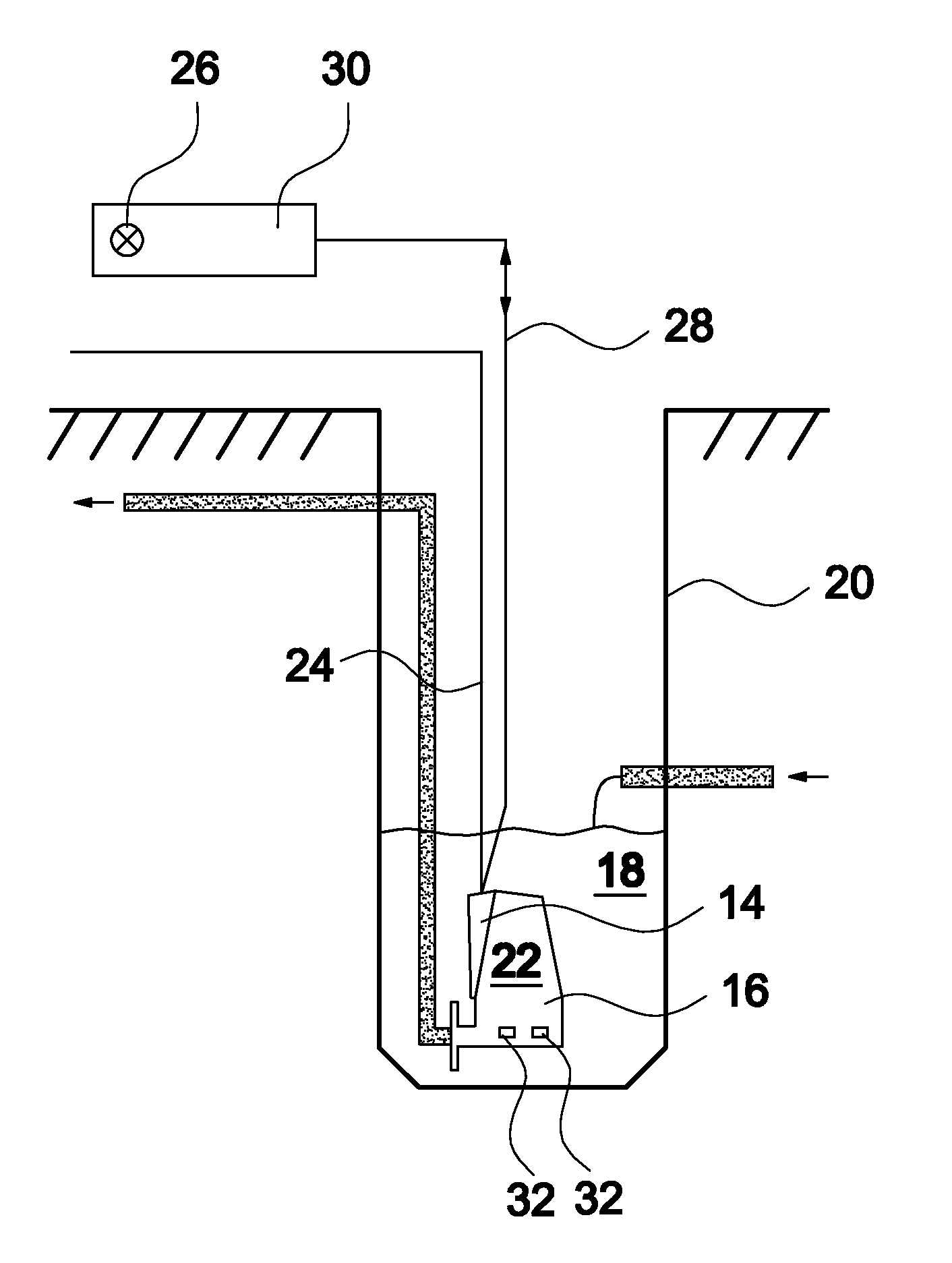
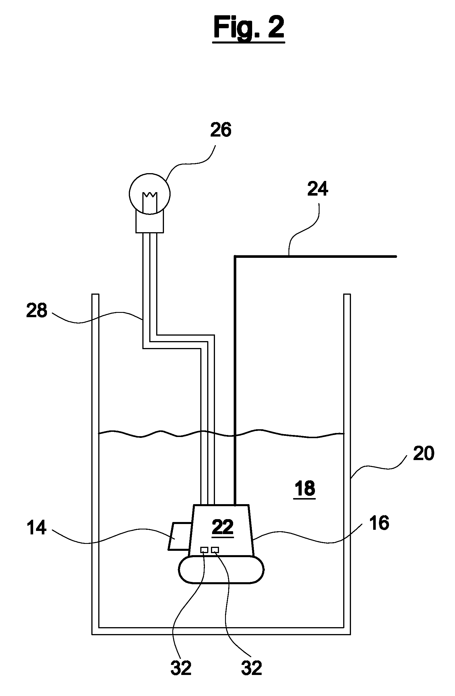
[0027]Referring to the drawings in detail, wherein like numerals indicate like elements throughout the several views, FIG. 2 shows a first preferred embodiment of the present invention. A control device 14 is arranged directly on a submersible pump 16 and submerges with this into a fluid 18 to be delivered, in a pump sump 20. The control device 14 may thereby be applied directly onto a motor housing 22 of the submersible pump 16 or may be also integrated into this. The control device 14 controls the operation of the drive motor in the inside of the motor housing 22 and then autonomously in the submersible pump 16, without an external c...


PUM


Abstract

An immersion pump assembly includes an electric drive motor and a control device (14) for controlling the drive motor, which are configured for dipping into a liquid (18) to be conveyed. An external display device (26) and / or an external communications device are / is configured for arrangement outside the liquid (18) to be conveyed and are / is connected to the control device (14) for signal transmission.

Description

CROSS-REFERENCE TO RELATED APPLICATIONS[0001]This application is a Section 371 of International Application No. PCT / EP2010 / 005389, filed Sep. 2, 2010, which was published in the German language on Apr. 14, 2011, under International Publication No. WO 2011 / 042096 A1 and the disclosure of which is incorporated herein by reference.BACKGROUND OF THE INVENTION[0002]The present invention relates generally to a submersible pump assembly with an electrical drive motor.[0003]Basically, two types of submersible pump assemblies are known from the state of the art. There are submersible pump assemblies with an electrical drive motor, which includes an electronic control or regulation device for the operation of the electrical drive motor. The device being arranged directly on the submersible electrical drive motor. These submersible pump assemblies merely require an electrical mains connection lead which leads into the pump sump. However, they provide no external control or monitoring possibili...

Claims


Application Information

Patent Timeline
Patent Type & Authority Patents(United States)
IPC IPC(8): F04B17/03F04D15/02F04D13/08F04D15/00
CPCF04D13/08F04D15/0088F04D15/0218F05B2260/80
Inventor ANDRESEN, JENS
Owner GRUNDFOS MANAGEMENT AS
Why Eureka
Try Eureka