
Vehicular mirror with blind spot indicator

a technology of blind spot indicator and vehicle mirror, which is applied in the direction of optical elements, instruments, transportation and packaging, etc., can solve the problems of blind spot accident, additional dangers, and reduced or obscured driver's visible field of view,

Active Publication Date: 2014-07-15
SMR PATENTS S A R L
View PDF16 Cites 24 Cited by
  • Summary
  • Abstract
  • Description
  • Claims
  • Application Information

AI Technical Summary

Benefits of technology

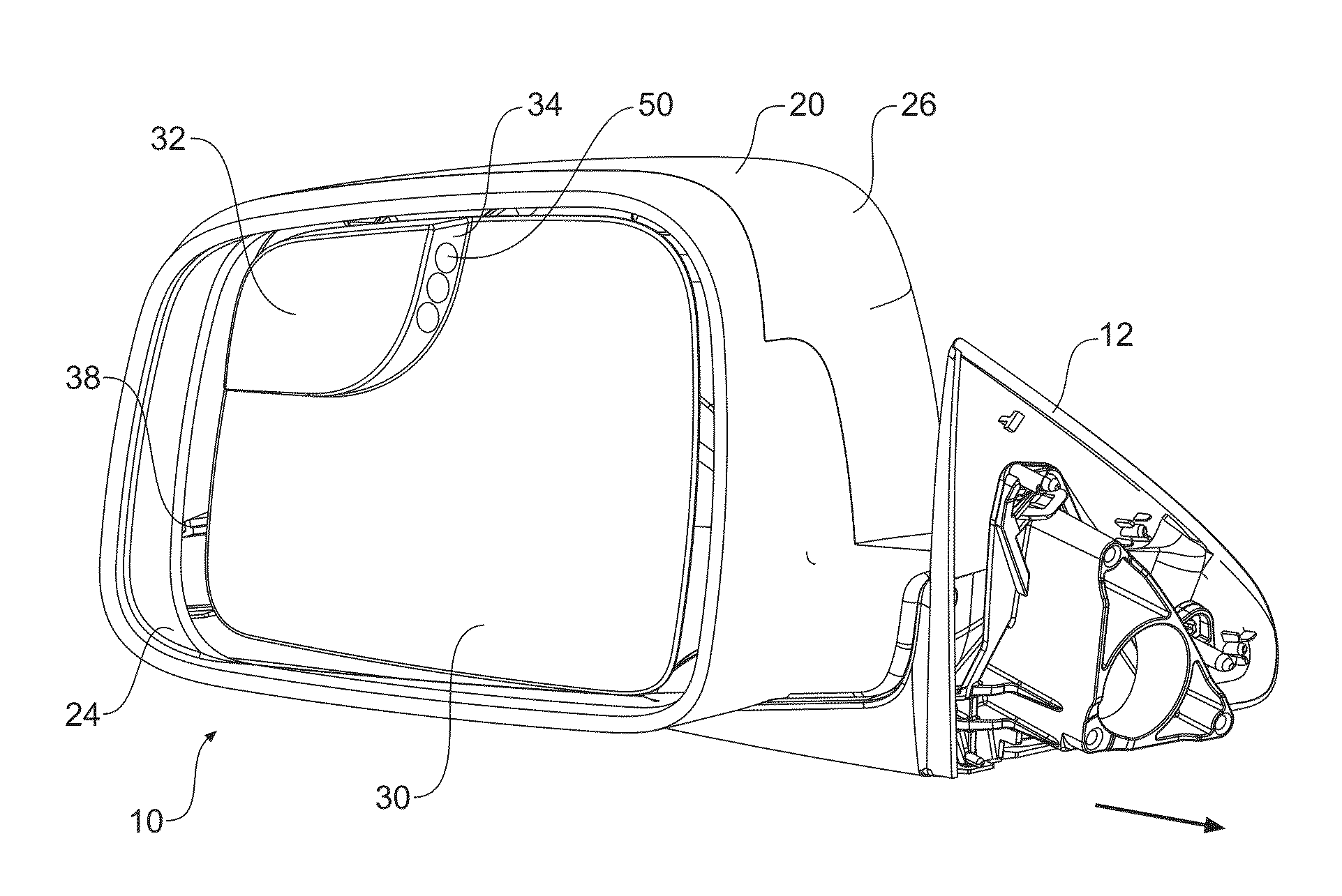
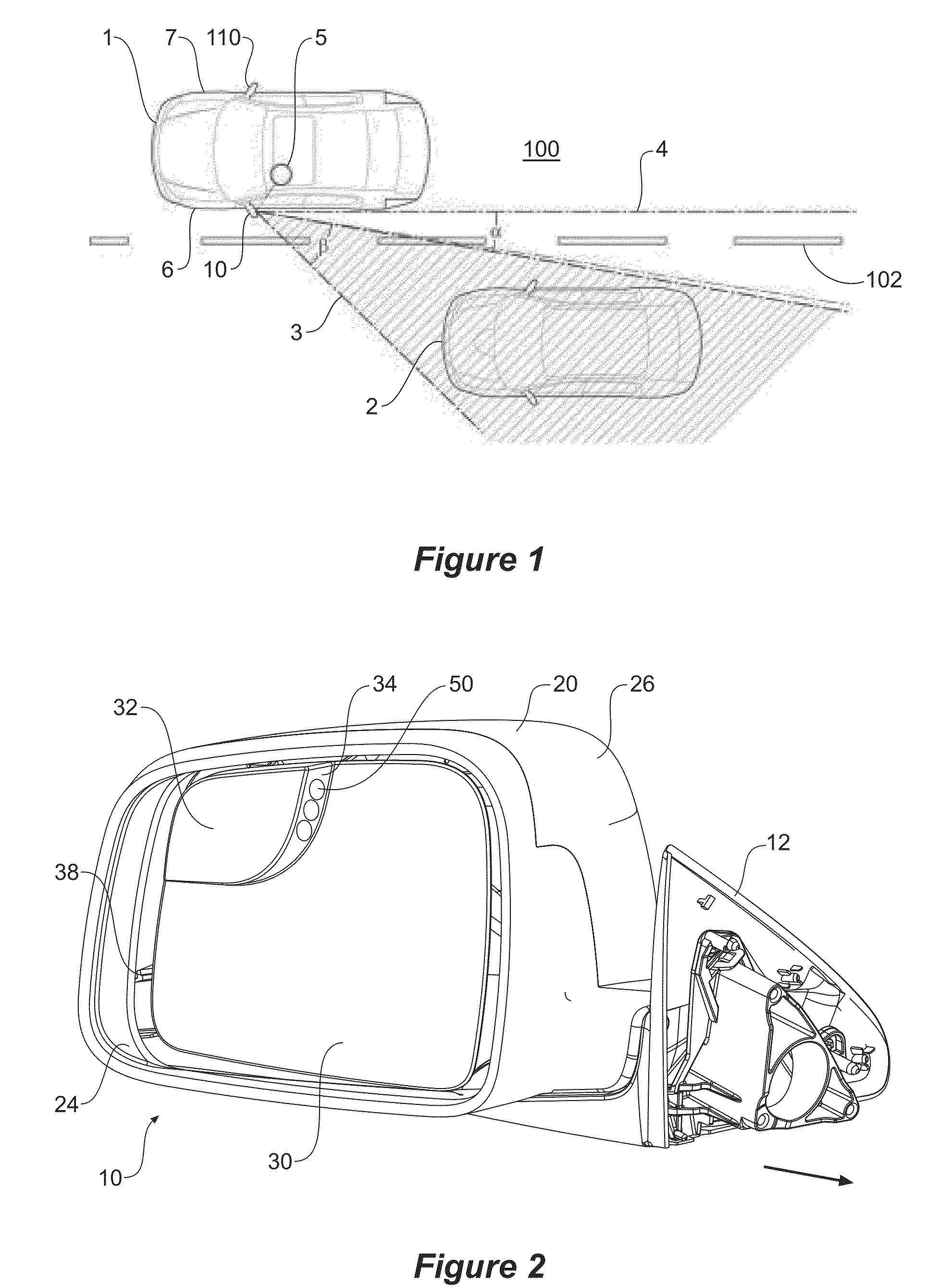
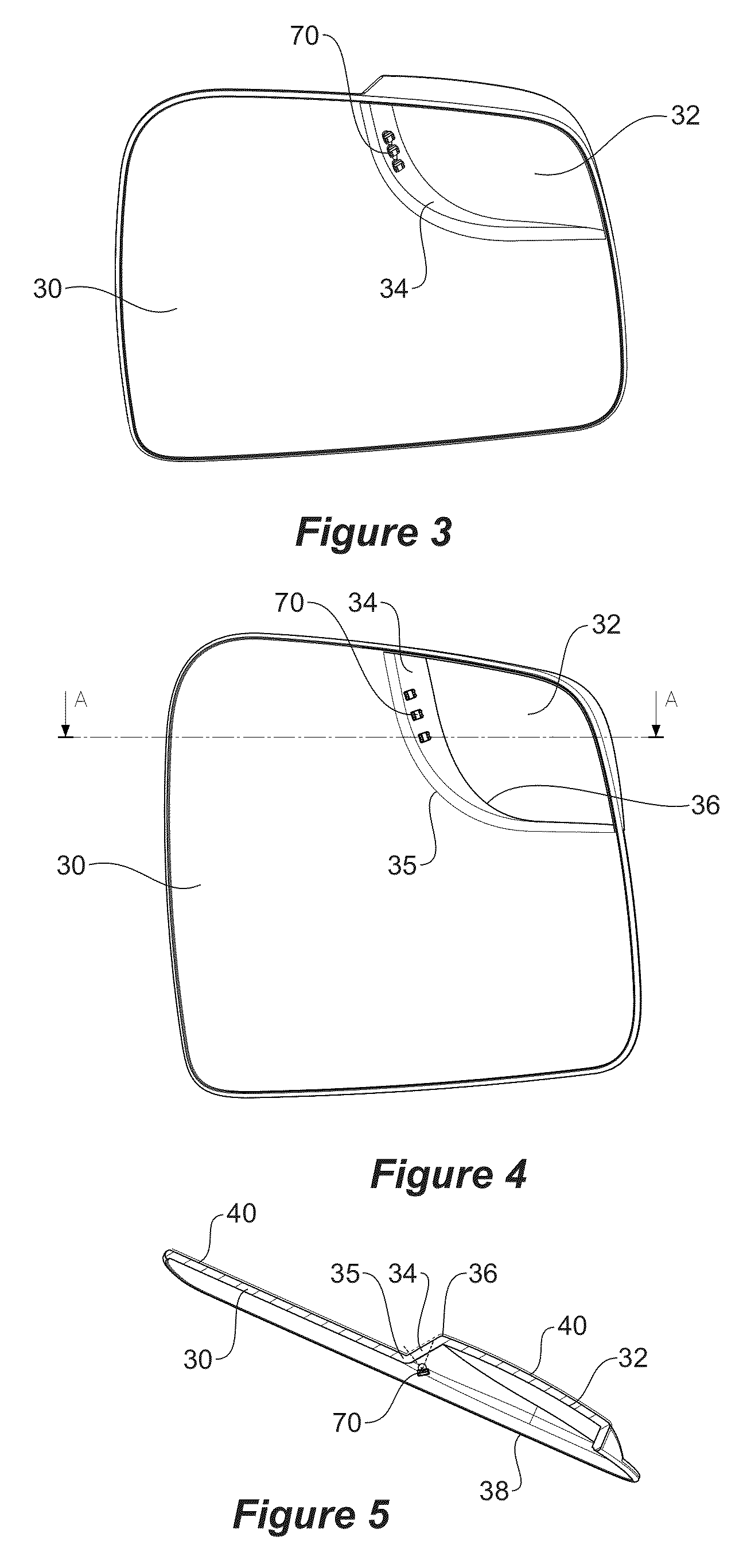
The invention is an exterior rear view mirror assembly for a motor vehicle that includes a first mirror surface for providing a rearward field of view to the driver, a second mirror surface for providing a rearward field of view to the driver of an object located in a blind zone of the vehicle, and a transition surface between the first and second mirror surfaces. The transition surface is oriented towards the driver and is designed to display a blind spot indicator when an object is detected in the vehicle's blind zone. The blind spot indicator can be a light source or a symbol on the transition surface. The assembly is made from a plastic polymer, such as polycarbonate or acrylic. The technical effect of the invention is to provide an improved rear view mirror assembly that can visually alert the driver of the vehicle to the presence of objects in their blind zone, increasing safety on the road.

Problems solved by technology

There is therefore an inherent danger that a blind spot accident may occur when changing lanes or attempting to overtake another vehicle.
This is cumbersome and requires the driver to take their eyes off the road in front of them which presents additional dangers.
A problem with known blind spot indicators, particularly illuminated markers and lighting displays is that they are often located in a region of the actual mirror surface such that when operable they partly reduce or obscure the driver's visible field of view.
These blind spot indicators for external rear view mirrors are also visible to other road users which may create a source of distraction or interference.
These locations are problematic as the field of view of the spotter mirror is either compromised by the blind spot indicator or in the case of the indicator (signalling light) around the periphery of the spotter mirror; the light would be easily visible to other road users and may become a source of distraction of interference.

Method used


Image

  • Vehicular mirror with blind spot indicator
  • Vehicular mirror with blind spot indicator
  • Vehicular mirror with blind spot indicator

Examples


Embodiment Construction

)

[0050]Referring now to FIG. 1, there is shown a plan view of a motor vehicle 1 driving along a road 100 that has a dashed line 102 designating a boundary of a lane of the road 100. The motor vehicle 1 has external rear view mirror (side mirror) assemblies 10 and 110 that extend outwards from lateral sides 6, 7 of the vehicle 1 respectively. The rear view mirror assembly 10 is located on the left hand side 6 of the vehicle 1 and is closest to a driver 5 of the vehicle 1. The rear view mirror assembly 10 is used by the driver 5 to view the road and any objects therein to the rear of the vehicle 1. The following description will focus on the rear view mirror assembly 10 that is on the driver side 6 of the vehicle 1. It will be appreciated by those skilled in the art that the following discussion with regard to the driver side rear view mirror assembly 10 applies equally to the passenger side rear view mirror assembly 110. In some countries, the driver 5 is located on the right hand si...


PUM


Abstract

An exterior rear view mirror assembly (10) for a motor vehicle (1) with a blind spot indicator for visually alerting a driver (5) to the presence of an object (2) in the blind spot (3) of the motor vehicle (1). The mirror assembly (10) includes a first mirror surface (30) and a second mirror surface (32). The mirror assembly (10) further includes a transition surface (34) disposed between the first and second mirror surfaces (30, 32) for displaying a blind spot indicator to the driver (5) when an object (2) is detected in the vehicle's blind spot (3). The transition surface (34) for displaying the blind spot indicator is oriented generally towards the driver of the vehicle and away from other road users. Preferably, the transition surface (34) forms a discrete step or discontinuity between the first and second mirror surfaces (30, 32).

Description

[0001]The present application claims priority from Australian Provisional Application No. 2011903207 entitled “Vehicular Mirror with Blind Spot Indicator,” and filed on 10 Aug. 2011, the entire content of which is hereby incorporated by reference in its entirety.BACKGROUND ART[0002]1. Field of the Invention[0003]The invention relates to external rear view mirrors for motor vehicles that allows a driver to observe objects located in a blind spot of the vehicle.[0004]2. Description of the Related Art[0005]The blind spot (or zone) of a motor vehicle is an area around the vehicle that cannot be directly observed by a driver with ease. The blind spots of most significance to a driver of a vehicle are the areas located adjacent to the rear quadrants of the vehicle. Objects in these areas may not be visible to a driver using a conventional rear view mirror (interior or exterior). There is therefore an inherent danger that a blind spot accident may occur when changing lanes or attempting to...

Claims


Application Information

Patent Timeline
Patent Type & Authority Patents(United States)
IPC IPC(8): B60Q1/00B60R1/08
CPCB60R1/081B60Q1/00B60R1/082B60R1/1207
Inventor BELCHER, SIMONMOASE, CHRISTOPHER
Owner SMR PATENTS S A R L
Learn More